How To Build A Voltage Regulator
The most confusing thing about making a voltage regulator is that you will need a piece called a "voltage regulator" to build one. This piece, by itself, will not do anything. By following these steps you will be able to assemble everything to make a working voltage regulator capable of taking in from seven to 30 volts and regulating it down to a steady five-volt output.
Step 1
The first thing you will need to do is identify the different leads on your regulator and orient your circuit breadboard.
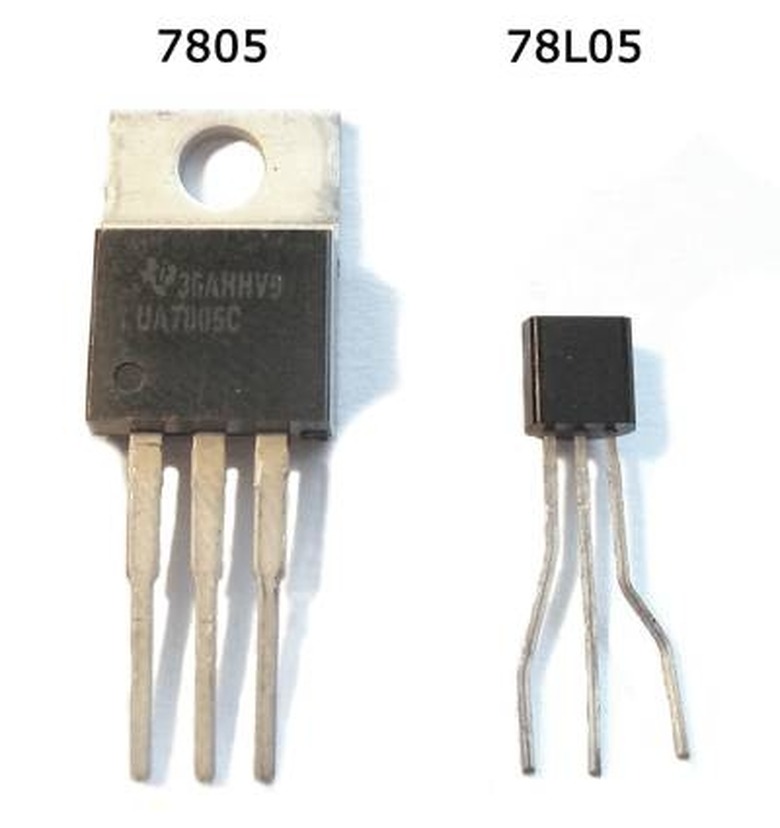
Hold the 7805 voltage regulator so that the printing is facing you. The lead on your left is the input lead. The middle lead is the ground. The lead on your right is your output.
Now, take your breadboard and lay it flat on your work surface so the length of the board runs from left to right and the shiny side is face down. The board is separated into three main areas. What we will call the bottom of the board is a series of holes that form a narrow rectangle and run from the left to the right. A similar series of holes runs across the top of the board. Both of these are referred to as "terminal strips." In the center there is a series of holes, also in a rectangular layout, but this layout is much wider then the ones on the bottom or top of your circuit board.
Place the breadboard on your work surface so the length of the board goes from left to right. Connect the ground wire of the transformer you want to use for the voltage regulator to one the long outer strip of the breadboard nearest you. Consider this the bottom of the breadboard.
Step 2
Take the 7805 voltage regulator and plug the output lead of the 7805 into the strip of holes at the top of the breadboard. The remaining leads, the ground and input should plug into the center area of the board.
Step 3
Connect the ground from the bottom terminal strip to the ground (middle lead) of the 7805 with a jumper wire.
Step 4
Connect the positive wire from the transformer to the input of the 7805. Remember, the input of your 7805 is the lead on the left if you are holding the 7805 with the printing facing towards you. Even if you use a different size or style of voltage regulator, the standard of manufacturing is that the printing is always on the same side to make identification of the leads possible.
Step 5
Now take your capacitor. Capacitors have both a positive and negative terminal, only one of them will be marked. A negative terminal will be marked with a (-) and a positive terminal will have a (+). Identify the positive terminal of the capacitor and connect it with the input lead of the 7805.
Step 6
Connect the output of the 7805 to the long outer terminal strip at the top of the breadboard.
Step 7
Connect the second capacitor between the output and ground leads of the 7805. The negative lead of the capacitor should go with the ground of the 7805 and the positive with input lead of the 7805.
Things Needed
- 7805 five-volt voltage regulator in a TO-220 case
- Two electrolytic capacitors (between 100 and 1000 mf)
- Electronic breadboard
- Jumper wire
TL;DR (Too Long; Didn't Read)
Use a multimeter with a thin electrical wire attached to the lead to test the breadboard to make sure the holes you are plugging your leads into are connected on the reverse side of the board. The resistance measured will be zero if they are connected.
Warning
Do not introduce more than 30 volts to this form of voltage regulator or you will burn out the components.
Cite This Article
MLA
Tribe, Cassandra. "How To Build A Voltage Regulator" sciencing.com, https://www.sciencing.com/build-voltage-regulator-4744989/. 24 April 2017.
APA
Tribe, Cassandra. (2017, April 24). How To Build A Voltage Regulator. sciencing.com. Retrieved from https://www.sciencing.com/build-voltage-regulator-4744989/
Chicago
Tribe, Cassandra. How To Build A Voltage Regulator last modified March 24, 2022. https://www.sciencing.com/build-voltage-regulator-4744989/