How To Calculate Amperage In A Series Circuit

Series circuits connect resistors such that the current, measured by amplitude or amperage, follows one path in the circuit and remains constant throughout. The current flows in the opposite direction of electrons through each resistor, which impede the flow of electrons, one after another in a single direction from the positive end of the battery to the negative. There are no external branches or paths through which the current can travel, as there would be in a parallel circuit.
Series Circuit Examples
Series Circuit Examples
Series circuits are common in everyday life. Examples include some types of Christmas or holiday lights. Another common example is a light switch. Additionally, computers, televisions and other household electronic devices all work through the concept of a series circuit.
TL;DR (Too Long; Didn't Read)
**In a series circuit, amperage, or amplitude, of the current remains constant and can be calculated using Ohm's law _V = I/R_ while the voltage drops across each resistor that can be summed up to get the total resistance. In contrast, in a parallel circuit, the amplitude of a current changes across the branching resistors while voltage remains constant.**
Amperage (or Amps) in a Series Circuit
Amperage (or Amps) in a Series Circuit
You can calculate the amplitude, in amps or amperes given by the variable A, of the series circuit by summing up the resistance at each resistor in the circuit as R and summing up the voltage drops as V, then solving for I in the equation V = I/R in which V is the voltage of the battery in volts, I is current, and R is the total resistance of the resistors in ohms (Ω). The voltage drop should be equal to the voltage of the battery in a series circuit.
The equation V = I/R, known as Ohm's Law, also holds true at each resistor in the circuit. The current flow throughout a series circuit is constant, which means it's the same at each resistor. You can calculate the voltage drop at each resistor using Ohms' Law. In series, the voltage of the batteries are increased, meaning they last a shorter length of time than if they were in parallel.
Series Circuit Diagram and Formula
Series Circuit Diagram and Formula
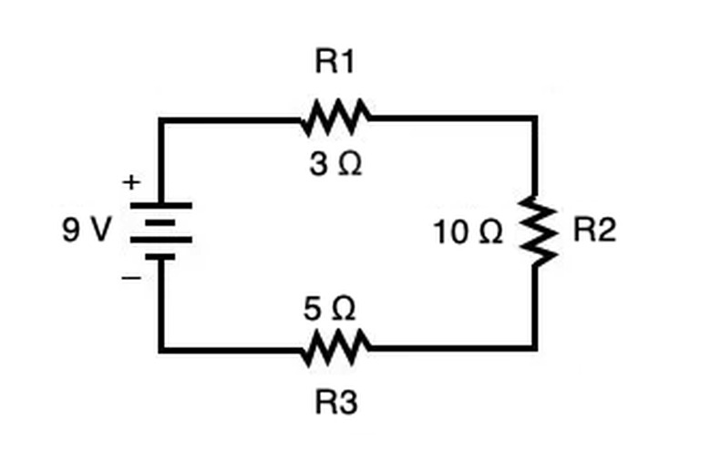
In the above circuit, each resistor (denoted by zig-zag lines) is connected to the voltage source, the battery (denoted by the + and – surrounding the disconnected lines), in series. Current flows in one direction and remains constant at each part of the circuit.
If you summed up each resistor, you would get a total resistance of 18 Ω (ohms, where ohm is the measure of resistance). This means you can calculate current using V = I/R in which R is 18 Ω and V is 9 V to get a current I of 162 A (amps).
Capacitors and Inductors
Capacitors and Inductors
In a series circuit, you can connect a capacitor with a capacitance C and let it charge over time. In this situation, current across the circuit is measured as
\(I=\frac{V}{R}e^{-t/(RC)}\)
in which V is in volts, R is in ohms, C is in Farads, t is time in seconds, and I is in amps. Here e refers to the Euler constant e.
The total capacitance of a series circuit is given by
\(\frac{1}{C_{total}}=\frac{1}{C_1}+\frac{1}{C_2}+...\)
in which each the inverse of each individual capacitor is summed on the right side (1/C_1_, 1/C_2_, etc.). In other words, the inverse of the total capacitance is the sum of the individual inverses of each capacitor. As time increases, the charge on the capacitor builds and the current slows down and approaches, but never fully reaches, zero.
Similarly, you can use an inductor to measure current
\(I=\frac{V}{R}e^{-tR/L}\)
in which the total inductance L is the sum of the inductance values of the individual inductors, measured in Henries. When a series circuit builds charge as a current flows, the inductor, a coil of wire that usually surrounds a magnetic core, generates a magnetic field in response to the flow of current. They can be used in filters and oscillators,
Series vs. Parallel Circuits
Series vs. Parallel Circuits
When dealing with circuits in parallel, in which the current branches through different parts of the circuits, the calculations are "flipped." Instead of determining the total resistance as the sum of individual resistances, the total resistance is given by
\(\frac{1}{R_{total}}=\frac{1}{R_1}+\frac{1}{R_2}+...\)
(the same way of calculating total capacitance of a series circuit).
The voltage, not the current, is constant throughout the circuit. The total parallel circuit current equals the sum of the current across each branch. You can calculate both current and voltage using Ohm's Law (V = I/R).
 Syed Hussain Ather
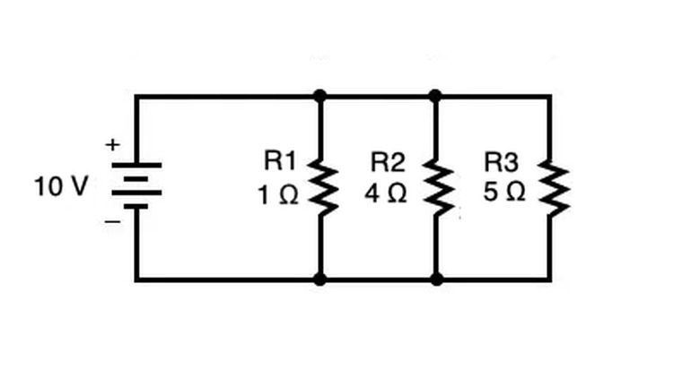
In the parallel circuit above, the total resistance would be given by the following four steps:
1. _1/Rtotal_ = 1/R1 + 1/R2 + 1/R3 2. _1/Rtotal_ = 1/1 Ω + 1/4 Ω + 1/5 Ω 3. _1/Rtotal_ = 20/20 Ω + 5/20 Ω + 4/20 Ω 4. _1/Rtotal_ = 29/20 Ω
5. Rtotal = 20/29 Ω or about .69 Ω
In the above calculation, note that you can only reach step 5 from step 4 when there is only one term on the left side (_1/Rtotal _) and only one term on the right side (29/20 Ω).
Likewise, the total capacitance in a parallel circuit is simply the sum of each individual capacitor, and the total inductance is also given by an inverse relationship (1/Ltotal = 1/L1 + 1/L2 + ... ).
Direct Current vs. Alternating Current
Direct Current vs. Alternating Current
In circuits, current can either flow constantly, as is the case in a direct current (DC), or fluctuate in a wave-like pattern, in alternating current circuits (AC). In an AC circuit, current changes between a positive and negative direction in the circuit.
British physicist Michael Faraday demonstrated the power of DC currents with the dynamo electric generator in 1832, but he couldn't transmit its power over long distances and the DC voltages required complicated circuits.
When the Serbian-American physicist Nikola Tesla created an induction motor using AC current in 1887, he demonstrated how it easily transmitted over long distances and could be converted between high and low values using transformers, a device used to change voltage. Soon enough, around the turn of the 20th-century households across America began discontinuing DC current in favor of AC.
Nowadays electronic devices use both AC and DC when appropriate. DC currents are used with semiconductors for smaller devices that only need to be turned on and off such as laptops and cell phones. AC voltage is transported through long wires before it is converted to DC using a rectifier or diode to power these appliances like light bulbs and batteries.
References
- All About Circuits: Simple Series Circuits
- BatteryStuff.com: Battery Bank Tutorial: Joining Batteries Via Series or Parallel for Increased Power
- Coilcraft: What is an inductor?
- Science ABC: DC vs AC: Direct Current (AC) Vs Alternating Current (DC)
- All About Circuits: Simple Parallel Circuits
- Reference: What Are Some Real Life Examples of Series Circuits?
Cite This Article
MLA
Ather, S. Hussain. "How To Calculate Amperage In A Series Circuit" sciencing.com, https://www.sciencing.com/calculate-amperage-series-circuit-6387840/. 27 December 2020.
APA
Ather, S. Hussain. (2020, December 27). How To Calculate Amperage In A Series Circuit. sciencing.com. Retrieved from https://www.sciencing.com/calculate-amperage-series-circuit-6387840/
Chicago
Ather, S. Hussain. How To Calculate Amperage In A Series Circuit last modified August 30, 2022. https://www.sciencing.com/calculate-amperage-series-circuit-6387840/