The Characteristics Of A Parallel Circuit

Electrical circuits can have their circuit elements arranged in either series or parallel. In series circuits, elements are connected using the same branch that sends electrical current through each of them one-by-one. In parallel circuits, the elements have their own separate branches. In these circuits, the current can take different paths throughout.
Because the current can take different paths in a parallel circuit, the current isn't constant throughout a parallel circuit. Instead, for branches that are connected in parallel with one another, the voltage or potential drop across each branch is constant. This is because the current distributes itself across each branch in amounts that are inversely proportional to the resistance of each branch. This causes the current to be the greatest where the resistance is least and vice versa.
These qualities let parallel circuits allow charge to flow through two or more paths, making it a standard candidate in homes and electrical devices through a stable and efficient power system. It lets electricity flow through other parts of a circuit when a part is damaged or broken, and they can distribute power equally across different buildings.These characteristics can be demonstrated through a diagram and an example of a parallel circuit.
Parallel Circuit Diagram
Parallel Circuit Diagram
In a parallel circuit diagram, you can determine the flow of electrical current by creating flows of electrical current from the positive end of the battery to the negative end. The positive end is given by the + on the voltage source, and the negative, -.
As you draw the way current travels throughout the branches of the parallel circuit, keep in mind that all the current entering one node or point in the circuit should equal all the current leaving or exiting that point. Also keep in mind that the voltage drops around any closed loop in the circuit should equal zero. These two statements are **Kirchhoff's circuit laws.**
Parallel Circuit Characteristics
Parallel Circuit Characteristics
Parallel circuits use branches that let current travel through different routes through the circuit. Current travels from the positive end of the battery or voltage source to the negative end. The voltage remains constant throughout the circuit while the current changes depending on the resistance of each branch.
TL;DR (Too Long; Didn't Read)
Parallel circuits are arranged such that current can travel through different branches simultaneously. Voltage, not current, is constant throughout, and Ohm's Law can be used to calculate voltage and current. In series-parallel circuits, the circuit can be treated as both a series and a parallel circuit.
Parallel Circuit Examples
Parallel Circuit Examples
To find the total resistance of resistors arranged in parallel with one another, use the formula
\(\frac{1}{R_{total}}=\frac{1}{R_1}+\frac{1}{R_2}+\frac{1}{R_3}+...+\frac{1}{R_n}\)
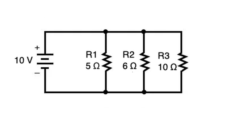
in which the resistance of each resistor is summed up on the right side of the equation. In the above diagram, the total resistance in ohms (Ω) can be calculated as follows:
1. 1/Rtotal = 1/5 Ω + 1/6 Ω + 1/10 Ω 2. 1/Rtotal = 6/30 Ω + 5/30 Ω + 3/30 Ω 3. 1/Rtotal = 14/30 Ω
4. Rtotal = 15/7 Ω or about 2.14 Ω
Note that you can only "flip" both sides of the equation from step 3 to step 4 when there is only one term on both sides of the equation (in this case, _1/Rtotal_ on the left and 14/30 Ω on the right).
After you have calculated the resistance, current and voltage can be calculated using Ohm's Law V = I/R in which V is voltage measured in volts, I is current measured in amps, and R is resistance in ohms. In parallel circuits, the sum of the currents through each path is the total current from the source. The current at each resistor in the circuit can be calculated by multiplying voltage times resistance for the resistor. Voltage remains constant throughout the circuit so voltage is the voltage of the battery or voltage source.
Parallel vs. Series Circuit
Parallel vs. Series Circuit
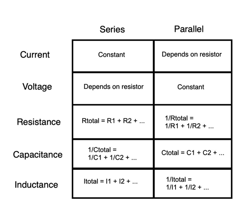
In series circuits, current is constant throughout, voltage drops depend on the resistance of each resistor and the total resistance is the sum of each individual resistor. In parallel circuits, voltage is constant throughout, current depends on each resistor and the inverse of the total resistance is the sum of the inverse of each individual resistor.
Capacitors and inductors can be used to alter the charge in series and parallel circuits over time. In a series circuit, the total capacitance of the circuit (given by the variable C), the potential of a capacitor to store charge over time, is the inverse sum of the inverses of each individual capacitance, and the total inductance (I), the power of inductors to give off charge over time, is the sum of each inductor. By contrast, in a parallel circuit, the total capacitance is the sum of each individual capacitor, and the inverse of the total inductance is the sum of the inverses of each individual inductance.
Series and parallel circuits also have different functions. In a series circuit, if one part is broken, current won't flow through the circuit at all. In a parallel circuit, an individual branch opening stops only the current in that branch. The rest of the branches will continue to work because the current has multiple paths it can take across the circuit.
Series-Parallel Circuit
Series-Parallel Circuit
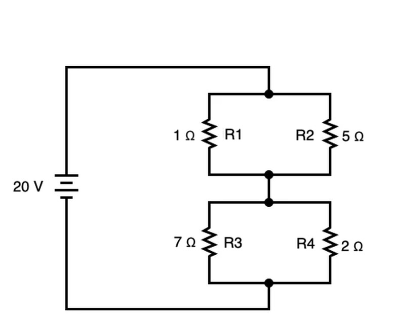
Circuits that have both branched elements that are also connected such that current flows in one direction between those branches are both series and parallel. In these cases, you can apply rules from both series and parallel as appropriate for the circuit. In the above example, R1 and R2 are in parallel with one another to form R5, and so are R3 and R4 to form R6. They can be summed in parallel as follows:
1. 1/R5 = 1/1 Ω + 1/5 Ω 2. 1/R5 = 5/5 Ω + 1/5 Ω 3. 1/R5 = 6/5 Ω
4. R5 = 5/6 Ω or about .83 Ω
1. 1/R6 = 1/7 Ω + 1/2 Ω 2. 1/R6 = 2/14 Ω + 7/14 Ω 3. 1/R6 = 9/14 Ω
4. R6 = 14/9 Ω or about 1.56 Ω
 Syed Hussain Ather
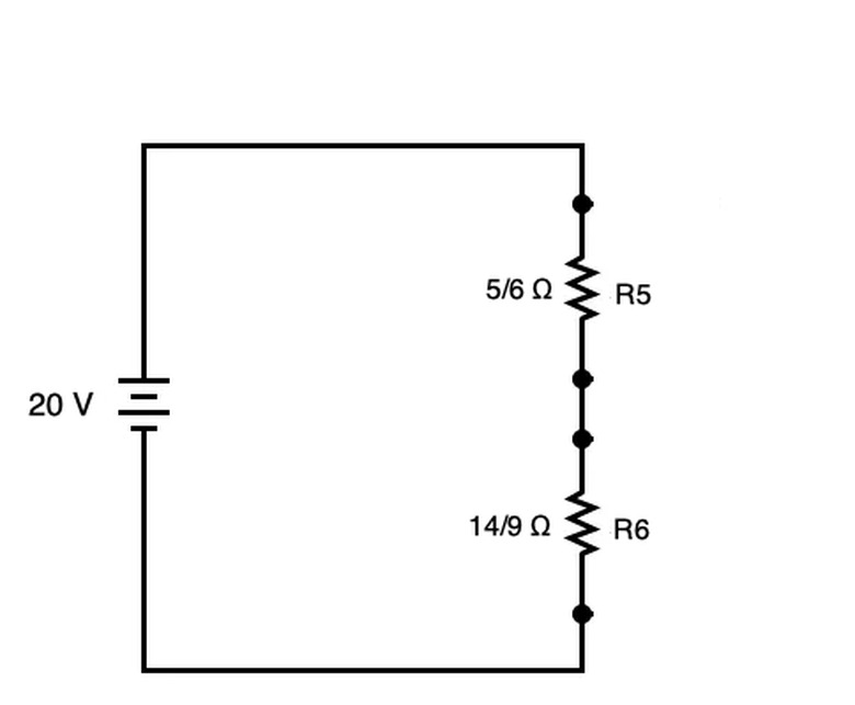
The circuit can be simplified to create the circuit shown directly above with R5 and R6. These two resistors can be added straightforwardly as though the circuit were series.
\(R_{total}=5/6\Omega+14/9\Omega=2.38\Omega\)
With 20 V as the voltage, Ohm's Law dictates that the total current equals V/R, or 20V / (43/18 Ω) = 360/43 A or about 8.37 A. With this total current, you can determine the voltage drop across both R5 and R6 using Ohms' Law (V=I/R) as well.
For R5,
\(V_5=\frac{360}{43}\times 5/6=6.98\text{ V}\)
For R6,
\(V_5=\frac{360}{43}\times 14/9=13.02\text{ V}\)
Finally, these voltage drops for R5 and R6 can be split back into the original parallelized circuits to calculate current of R1 and R2 for R5 and R2 and R3 for R6 using Ohm's Law.
I1 = (1800/258 V) / 1 Ω = 1800/258 A or about 6.98 A.
I2 = (1800/258 V) / 5 Ω = 1500/43 A or about 34.88 A.
I3 = (680/129 V) / 7 Ω = 4760/129 A or about 36.90 A.
I3 = (680/129 V) / 2 Ω = 1360/129 A or about 10.54 A.
Cite This Article
MLA
Ather, S. Hussain. "The Characteristics Of A Parallel Circuit" sciencing.com, https://www.sciencing.com/characteristics-parallel-circuit-8326545/. 27 December 2020.
APA
Ather, S. Hussain. (2020, December 27). The Characteristics Of A Parallel Circuit. sciencing.com. Retrieved from https://www.sciencing.com/characteristics-parallel-circuit-8326545/
Chicago
Ather, S. Hussain. The Characteristics Of A Parallel Circuit last modified March 24, 2022. https://www.sciencing.com/characteristics-parallel-circuit-8326545/