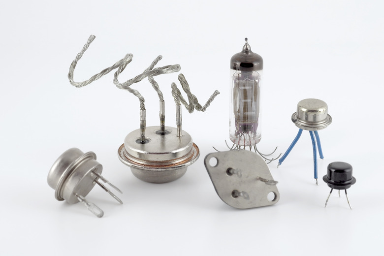
Characteristics Of Silicon & Germanium Diodes
When we think of electronic devices, we often think about how fast these devices operate or how long we can operate the device before recharging the battery. What most people don't think about is what the components in their electronic devices are made of. While each device differs in its construction, these devices all have one thing in common – electronic circuits with components that contain the chemical elements silicon and germanium.
TL;DR (Too Long; Didn't Read)
Silicon and germanium are two chemical elements called metalloids. Both silicon and germanium can be combined with other elements called dopants to create solid-state electronic devices, such as diodes, transistors and photoelectric cells. The primary difference between silicon and germanium diodes is the voltage needed for the diode to turn on (or become "forward-biased"). Silicon diodes require 0.7 volts to become forward-biased, whereas germanium diodes require only 0.3 volts to become forward-biased.
How to Cause Metalloids to Conduct Electric Currents
How to Cause Metalloids to Conduct Electric Currents
Germanium and silicon are chemical elements called metalloids. Both elements are brittle and have a metallic luster. Each of these elements has an outer electron shell that contains four electrons; this property of silicon and germanium makes it difficult for either element in its purest form to be a good electrical conductor. One way to cause a metalloid to conduct electric current freely is to heat it up. Adding heat causes the free electrons in a metalloid to move faster and travel more freely, allowing applied electric current to flow if the difference in voltage across the metalloid is enough to jump into the conduction band.
Introducing Dopants to Silicon and Germanium
Introducing Dopants to Silicon and Germanium
Another way to change the electrical properties of germanium and silicon is to introduce chemical elements called dopants. Elements such as boron, phosphorus or arsenic can be found on the periodic table near silicon and germanium. When dopants are introduced to a metalloid, the dopant either provides an extra electron to the outer electron shell of the metalloid or deprives the metalloid of one of its electrons.
In the practical example of a diode, a piece of silicon is doped with two different dopants, such as boron on one side and arsenic on the other. The point where the boron-doped side meets the arsenic-doped side is called a P-N junction. For a silicon diode, the boron-doped side is called "P-type silicon" because the introduction of boron deprives the silicon of an electron or introduces an electron "hole." On the other side, arsenic-doped silicon is called "N-type silicon" because it adds an electron, which makes it easier for electric current to flow when voltage is applied to the diode.
Since a diode acts as a one-way valve for the flow of electrical current, there must be a voltage differential applied to the two halves of the diode, and it must be applied in the correct regions. In practical terms, this means that the positive pole of a power source must be applied to the wire going to the P-type material, while the negative pole must be applied to the N-type material for the diode to conduct electricity. When power is applied properly to a diode, and the diode is conducting electric current, the diode is said to be forward-biased. When the negative and positive poles of a power source are applied to the opposite-polarity materials of a diode – positive pole to N-type material and negative pole to P-type material – a diode does not conduct electric current, a condition known as reverse-bias.
The Difference Between Germanium and Silicon
The Difference Between Germanium and Silicon
The chief difference between germanium and silicon diodes is the voltage at which electric current begins to flow freely across the diode. A germanium diode typically begins to conduct electric current when voltage properly applied across the diode reaches 0.3 volts. Silicon diodes require more voltage to conduct current; it takes 0.7 volts to create a forward-bias situation in a silicon diode.
Cite This Article
MLA
Sandoval, David. "Characteristics Of Silicon & Germanium Diodes" sciencing.com, https://www.sciencing.com/characteristics-silicon-germanium-diodes-6823105/. 17 April 2018.
APA
Sandoval, David. (2018, April 17). Characteristics Of Silicon & Germanium Diodes. sciencing.com. Retrieved from https://www.sciencing.com/characteristics-silicon-germanium-diodes-6823105/
Chicago
Sandoval, David. Characteristics Of Silicon & Germanium Diodes last modified March 24, 2022. https://www.sciencing.com/characteristics-silicon-germanium-diodes-6823105/
