How Does A Rectifier Work?
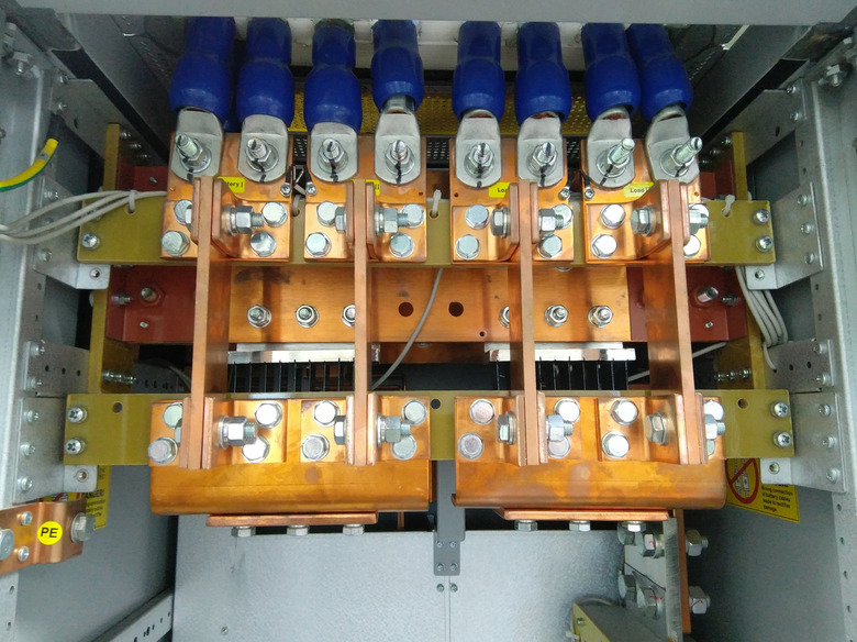
You may wonder how power lines send electric currents across long distances for different purposes. And there are different "types" of electricity. The electricity that powers electric railway systems may not be appropriate for household appliances like phones and television sets. Rectifiers help by converting between these different types of electricity.
Bridge Rectifier and Rectifier Diode
Bridge Rectifier and Rectifier Diode
Rectifiers let you convert from alternating current (AC) to direct current (DC). AC is current that switches between flowing backwards and forwards at regular intervals while DC flows in a single direction. They generally rely on a bridge rectifier or a rectifier diode.
All rectifiers use P-N junctions, semiconductor devices that let electric current flow in only a single direction from the formation of p-type semiconductors with n-type semiconductors. The "p" side has an excess of holes (locations where there are no electrons) so it is positively charged. The "n" side is negatively charged with electrons in their outer shells.
Many circuits with this technology are built with a bridge rectifier. Bridge rectifiers convert AC to DC using its system of diodes made of a semiconductor material in either a half wave method that rectifiers one direction of the AC signal or a full wave method that rectifies both directions of the input AC.
Semiconductors are materials that let current flow because they're made of metals like gallium or metalloids like silicon that are contaminated with materials like phosphorous as a means of controlling current. You can use a bridge rectifier for different applications for a wide range of currents.
Bridge rectifiers also have the advantage of outputting more voltage and power than other rectifiers. Despite these benefits, bridge rectifiers suffer from having to use four diodes with the extra diodes compared to other rectifiers, causing a voltage drop that decreases the output voltage.
Silicon and Germanium Diodes
Silicon and Germanium Diodes
Scientists and engineers generally use silicon more frequently than germanium in creating diodes. Silicon p-n junctions work more effectively at higher temperatures than germanium ones. Silicon semiconductors let electric current flow more easily and can be created with lower costs.
These diodes take advantage of the p-n junction to convert AC to DC as a sort of electric "switch" that lets current flow in either the forward or reverse direction based on the p-n junction direction. Forward biased diodes let current continue to flow while reverse biased diodes block it. This is what causes silicon diodes to have a forward voltage of about 0.7 volts so that they only lets current flow if it's more than volts. For germanium diodes, the forward voltage is 0.3 volts.
The anode terminal of a battery, electrode or other voltage source where oxidization occurs in a circuit, supplies the the holes to the cathode of a diode in forming the p-n junction. In contrast, the cathode of a voltage source, where reduction occurs, provides the electrons that are sent to the anode of the diode.
Half Wave Rectifier Circuit
Half Wave Rectifier Circuit
You can study how half wave rectifiers are connected in circuits to understand how they work. Half wave rectifiers switch between being forward biased and reverse biased based on the positive or negative half cycle of the input AC wave. It sends this signal to a load resistor such that the current flowing through the resistor is proportional to voltage. This happens due to Ohm's Law, which represents voltage V as the product of current I and resistance R in
\(V=IR\)
You can measure the voltage across the load resistor as the supply voltage _Vs_, which is equal to the output DC voltage _Vout_. The resistance associated with this voltage also depends on the diode of the circuit itself. Then, the rectifier circuit switches to being reverse biased in which it takes the negative half cycle of the input AC signal. In this case, no current flows through the diode or the circuit and the output voltage drops to 0. The output current is, then, unidirectional.
Full wave Rectifier Circuit
Full wave Rectifier Circuit
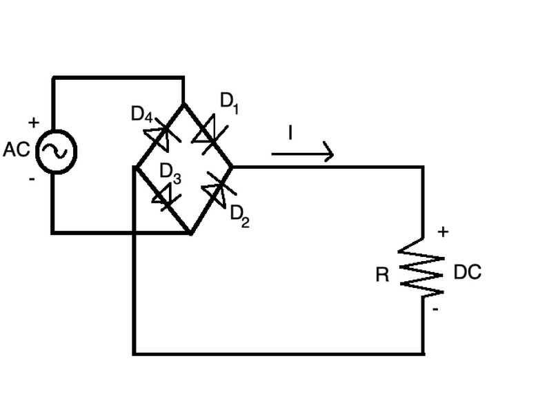
Full wave rectifiers, in contrast, use the entire cycle (with positive and negative half cycles) of the input AC signal. The four diodes in a full wave rectifier circuit are arranged such that, when the AC signal input is positive, the current flows across the diode from _D1_ to the load resistance and back to the AC source through _D2_. When the AC signal is negative, the current takes the _D3_-load-_D4_ path instead. The load resistance also outputs the DC voltage from the full wave rectifier.
The average voltage value of a full wave rectifier is twice that of a half wave rectifier, and the root mean squared voltage, a method of measuring AC voltage, of a full wave rectifier is √2 times that of a half wave rectifier.
Rectifier Components and Applications
Rectifier Components and Applications
Most of the electronic appliances in your household use AC, but some devices like laptops convert this current to DC before using it. Most laptops use a type of Switched Mode Power Supply (SMPS) that lets the output DC voltage more power for the size, cost and weight of the adapter.
SMPS work using a rectifier, oscillator and filter that control pulse width modulation (a method of reducing the power of an electric signal), voltage and current. The oscillator is an AC signal source from which you can determine amplitude of current and the direction it flows. The laptop's AC adapter then uses this to connect to the AC power source and converts the high AC voltage to low DC voltage, a form it can use to power itself, during charging.
Some rectifier systems also use a smoothing circuit or capacitor that lets them output a constant voltage, instead of one that varies over time. The electrolytic capacitor of smoothing capacitors can achieve capacitances between 10 to thousands of microfarads (µF). More capacitance is necessary for greater input voltage.
Other rectifiers make use of transformers which alter voltage using four-layered semiconductors known as thyristors alongside diodes. A silicon-controlled rectifier, another name for a thyristor, uses a cathode and an anode separated by a gate and its four layers to create two p-n junctions arranged one on top of the other.
Uses of Rectifier Systems
Uses of Rectifier Systems
The types of rectifier systems vary across applications in which you need to alter voltage or current. In addition to the applications already discussed, rectifiers find use in soldering equipment, electric welding, AM radio signals, pulse generators, voltage multipliers and power supply circuits.
Soldering irons that are used to connect parts of electric circuits together use half wave rectifiers for a single direction of the input AC. Electric welding techniques that use bridge rectifier circuits are ideal candidates for providing supply steady, polarized DC voltage.
AM radio, which modulates amplitude, can use half wave rectifiers to detect changes in electric signal input. Pulse generating circuits, which generate rectangular pulses for digital circuits use half wave rectifiers for changing the input signal.
Rectifiers in power supply circuits convert AC to DC from different power supplies. This is useful as DC is generally sent across long distances before it is converted to AC for household electricity and electronic devices. These technologies make great use of the bridge rectifier that can handle the change in voltage.
References
- Physics and Radio Electronics: Rectifier
- Science ABC: What Are Semiconductors? And How Do They Work?
- The Verge: Gallium nitride is the silicon of the future
- El Pro Cus: Bridge Rectifier – Basics & Application
- Physics and Radio Electronics: P-N junction semiconductor diode
- All About Circuits: Introduction to Diodes And Rectifiers
- Learn About Electronics: Switched Mode Power Supplies
- Learning About Electronics: What's a Smoothing Capacitor?
- Mini Physics: Rectification
- Corrosionpedia: Transformer Rectifier
- Explain That Stuff: Thyristors
- EdgeFX: What is a Rectifier? Explain Different Types of Rectifiers
- BYJUS: Uses of Rectifier
- Physics and Radio Electronics: Half wave Rectifier
- Sciencedirect: Single-Phase Rectifier
Cite This Article
MLA
Ather, S. Hussain. "How Does A Rectifier Work?" sciencing.com, https://www.sciencing.com/a-rectifier-work-4964589/. 27 December 2020.
APA
Ather, S. Hussain. (2020, December 27). How Does A Rectifier Work?. sciencing.com. Retrieved from https://www.sciencing.com/a-rectifier-work-4964589/
Chicago
Ather, S. Hussain. How Does A Rectifier Work? last modified March 24, 2022. https://www.sciencing.com/a-rectifier-work-4964589/

