The Advantages & Disadvantages Of Series And Parallel Circuits
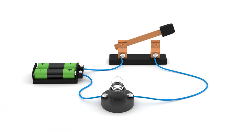
Electrical circuits deliver electrical power from a source to devices that use it, such as a light bulb or a speaker. Circuits come in two basic varieties, series and parallel; each type has advantages and disadvantages for managing voltage and current. Wiring components in series means they are connected one after the other, whereas parallel wiring involves a ladder-like connection where components are like the "rungs" of the ladder.
TL;DR (Too Long; Didn't Read)
A series circuit shares the same current among its components; a parallel circuit shares the same voltage.
Power Sources in Series versus Parallel
Power Sources in Series versus Parallel
An electrical source, such as a battery or power supply, creates a voltage difference across the circuit that drives electrical current. From Ohm's law, the greater the voltage, the greater the current. With batteries wired in series, the total voltage is the sum of the individual voltages. For instance, three 5-volt batteries in series produce a total of 15 volts. By contrast, the voltage for batteries in parallel do not add up, though their capacities do. This means if one 5-volt battery powers a circuit for two hours, two 5-volt batteries in parallel would last four hours, but supply only 5 volts total.
Resistors in Series versus Parallel
Resistors in Series versus Parallel
Resistors reduce the current that a circuit delivers to the device using the electrical power. This is necessary to protect current-sensitive components and regulate the current in the circuit. Resistance is measured in units called ohms. Much like the voltage of batteries, resistors that are wired in series yield added overall resistance. Three 2-ohm resistors wired in series give a total of 6 ohms of resistance. To calculate total resistance for resistors in parallel, you use the following formula:
\(\frac{1}{R_{tot}}=\frac{1}{R_1}+\frac{1}{R_2}+\frac{1}{R_3}+...\)
For example, for three 2-ohm resistors in parallel:
\(R_{tot}=\frac{1}{1/2 + 1/2 + 1/2} = 0.67\text{ ohms}\)
Switches in Series versus Parallel
Switches in Series versus Parallel
Switches let you turn a circuit on or off. When a switch is closed, current flows, whereas open switches break the circuit and stop the flow. For multiple switches wired in series, it takes only one open switch to stop the current. This can be useful when you have a long circuit and want to be able to turn it off and on from different places, such as when multiple light switches control the light in the center of the room. However, with switches wired in parallel, all of them must be open to stop the flow of current. Different combinations of opened and closed parallel circuits can redirect current to different components—such as resistors, powered devices and power supplies—within the circuit.
References
Cite This Article
MLA
Banas, Timothy. "The Advantages & Disadvantages Of Series And Parallel Circuits" sciencing.com, https://www.sciencing.com/advantages-disadvantages-series-parallel-circuits-6306911/. 5 December 2020.
APA
Banas, Timothy. (2020, December 5). The Advantages & Disadvantages Of Series And Parallel Circuits. sciencing.com. Retrieved from https://www.sciencing.com/advantages-disadvantages-series-parallel-circuits-6306911/
Chicago
Banas, Timothy. The Advantages & Disadvantages Of Series And Parallel Circuits last modified March 24, 2022. https://www.sciencing.com/advantages-disadvantages-series-parallel-circuits-6306911/
