How Does A Digital To Analog Converter Work?
Electronics and equipment that you use in your everyday life need to transform data and input sources into other formats. For digital audio equipment, the way an MP3 file produces sound relies upon converting between analog and digital formats of data. These digital-to-analog converters (DACs) take input digital data and convert them into analog audio signals for these purposes.
How Digital to Audio Converters Work
How Digital to Audio Converters Work
The sound that these audio equipment produce are the analog form of digital input data. These converters let audio be converted from a digital format, an easy-to-use type of audio that computers and other electronics, to an analog format, made of variations in air pressure that produce sound itself.
DACs take a binary number of the digital form of audio and turns it into an analog voltage or current that, when done entirely over the course of a song, can create a wave of audio that represents the digital signal. It creates the analog version of the digital audio in "steps" of each digital reading.
Before it creates the audio, the DAC creates a stair step wave. This is a wave in which there's a small "jump" between each digital reading. To convert these jumps into a smooth, continuous analog reading, DACs use interpolation. This is a method of looking at two points next to one another on the stair step wave and determining the values in between them.
This makes the sound smooth and less distorted. DACs output these voltages that have smoothed into a continuous waveform. In contrast to DAC, a microphone that picks up audio signals uses an analog-to-digital converter (ADC) to create a digital signal.
ADC and DAC Tutorial
ADC and DAC Tutorial
While a DAC converts a digital binary signal to an analog one such as voltage, an ADC does the reverse. It takes an analog source and converts it to a digital one. Used together, for a DAC, the converter and an ADC converter can make up a large portion of the technology of audio engineering and recording. The way they're both used makes for applications in communication technology that you can learn about through an ADC and DAC tutorial.
The same way a translator may transforms words into other words between languages, ADCs and DACs work together in letting people communicate over long distances. When you call someone over the phone, your voice is converted into an analog electrical signal by a microphone.
Then, an ADC converts the analog signal into a digital one. The digital currents are sent through network packets, and, when they reach the destination, they're converted back into an analog electrical signal by a DAC.
These designs must take into account the features of communicating through ADCs and DACs. The number of measurements the DAC takes at each second is the sample rate or sampling frequency. A higher sample rate lets the devices achieve greater accuracy. Engineers must also create equipment with a large number of bots that represent the number of steps used, as described above, to represent the voltage at a given point in time.
The more steps, the higher the resolution. You can determine the resolution by taking 2 to the power of the number of bits of the DAC or ADC that creates the analog or digital signal, respectively. For an 8-bit ADC, the resolution would be 256 steps.
Digital to Analog Converter Formula
Digital to Analog Converter Formula
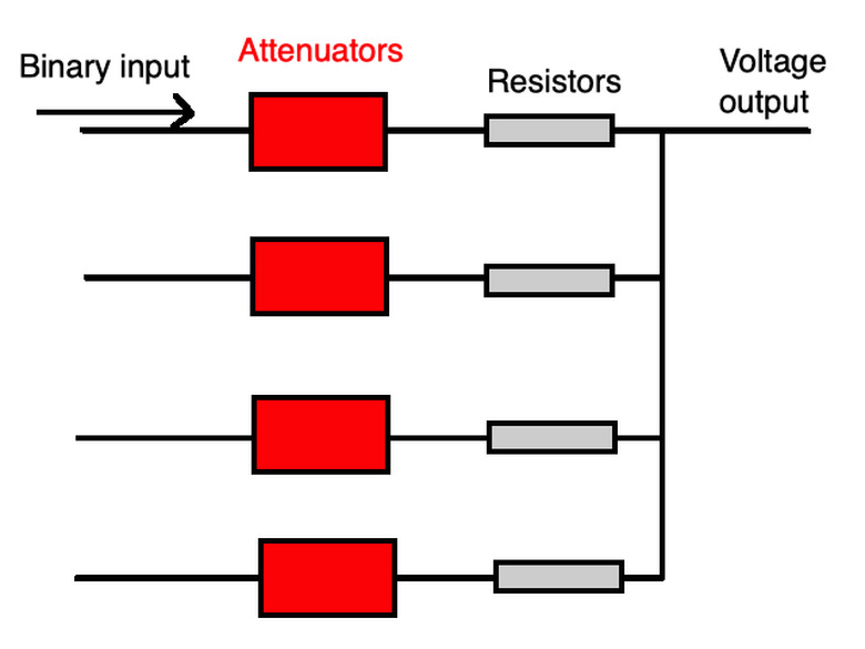
A DAC converter turns a binary into a voltage value. This value is the voltage output as seen in the diagram above. You can calculate the output voltage as
\(V_{out}=\frac{V_4G_4+V_3G_3+V_2G_2+V_1G_1}{G_4+G_3+G_2+G_1}\)
for the voltages V across each attenuator and the conductance G of each attenuator. The attenuators are part of the process in creating the analog signal to reduce distortion. They're connected in parallel so each individual conductance sums up this way through this digital to analog converter formula.
You can use Thevenin's theorem to relate the resistance of each attenuator to its conductance. The Thevenin resistance is
\(R_t=\frac{1}{G_4+G_3+G_2+G_1}\)
Thevenin's theorem states, "Any linear circuit containing several voltages and resistances can be replaced by just one single voltage in series with a single resistance connected across the load." This lets you calculate quantities from a complicated circuit as though it were a simple one.
Remember you can also use **Ohm's Law,** V = IR for voltage V, current I and resistance R when dealing with these circuits and any digital to analog converter formula. If you know the resistance of a DAC converter, you can use a circuit with a DAC converter in it to measure the output voltage or current.
ADC Architectures
ADC Architectures
There are many popular ADC architectures such as successive approximation register (SAR), Delta-Sigma (∆∑) and Pipeline converters. The SAR turns an input analog signal into a digital one by "holding" the signal. This means searching the continuous analog waveform through a binary search that looks through all possible quantization levels before finding a digital output for each conversion.
Quantization is a method of mapping a large set of input values from a continuous waveform to output values that are fewer in number. The SAR ADCs are generally easy to use with lower power use and igh accuracy.
Delta-Sigma designs find the average of the sample over the time that it uses as the input digital signal. The average over the difference in time of the signal itself is represented using the Greek symbols delta (∆) and sigma (∑), giving it its name. This method of ADCs has a high resolution and high stability with low power use and cost.
Finally, Pipeline converters use two stages that "hold" it like SAR methods and send the signal through various step such as flash ADCs and attenuators. A flash ADC compares each input voltage signal over a small sample of time to a reference voltage to create a binary digital output. Pipeline signals are generally at higher bandwidths, but with lower resolution and need more power to run.
Digital to Analog Converter Working
Digital to Analog Converter Working
One widely used DAC design is the R-2R network. This uses two resistors values with one twice as large as the other. This lets R-2R scale easily as a method of using resistors to attenuate and transform the input digital signal and get the digital to analog converter working.
A binary-weighted resistor is another common example of DAC. These devices use resistors with outputs that meet at the single resistor that sums up the resistances. The more significant parts of the input digital current will give greater output current. More bits of this resolution will allow more current to flow through.
Practical Applications of Converters
Practical Applications of Converters
MP3s and CDs store audio signals in digital formats. This means DACs are used in CD players and other digital devices that produce sounds like sound cards for computers and video games. DACs that create analog line-level output can be used in amplifiers or even USB speakers.
These applications of DACs typically rely on a constant input voltage or current to create the output voltage and get the digital to analog converter working. Multiplying DACs can use varying input voltage or current sources, but they have constraints on the bandwidth they can use.
References
- Sweetwater: What Is a Digital-to-Analog Converter and How Does It Work?
- Audio Advice: What is a DAC (Digital-to-Analog Converter) and How Does it Work?
- Macao: Digital to Analog Converter
- Analog Devices: Analog-Digital Conversion
- Imperial College London: Digital-to-Analogue Conversion
- Analog Devices: Multiplying DACs
- All About Circuits: Flash ADC
Cite This Article
MLA
Ather, S. Hussain. "How Does A Digital To Analog Converter Work?" sciencing.com, https://www.sciencing.com/analog-digital-converter-work-4968312/. 27 December 2020.
APA
Ather, S. Hussain. (2020, December 27). How Does A Digital To Analog Converter Work?. sciencing.com. Retrieved from https://www.sciencing.com/analog-digital-converter-work-4968312/
Chicago
Ather, S. Hussain. How Does A Digital To Analog Converter Work? last modified August 30, 2022. https://www.sciencing.com/analog-digital-converter-work-4968312/

