How To Build An LED Electric Counter
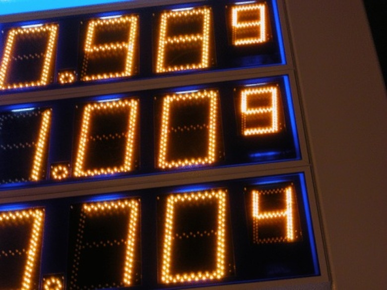
An LED electronic counter lets you design circuits like digital clocks and stop watches. In the basic configuration, a binary coded decimal (BCD) counter is used to drive a seven-segment display driver which connects to a seven-segment LED (light emitting diode). Each time you apply a voltage pulse to the input of the counter, the counter value increases. This changes the digital voltage levels on the outputs of the display driver. This in turn lights the different segments on the seven-segment LED to produce different numbers, such as 0, 1, 2, 3, 4, 5, 6, 7, 8 and 9.
Step 1
Call the 7490 BCD counter part "A", the 7447 part "B" and the seven-segment LED display part "C." Place part A, B, and C into your electronic breadboard. Now insert the 470-Ohm resistors into the electronic breadboard between part B and part C. Name each 470-Ohm resistor. Use Ra, Rb, Rc, Rd, Re, Rf and Rg as their names.
Step 2
Connect pins 2, 3, 6, 7 and 11 together and call this point "ground." Connect the positive terminal of the pulse generator to pin 14 of part A. Connect the negative terminal of the pulse generator to ground. Connect pin 1 and 2 of part A to pin 7 of part B. Connect pin 9 of part A to pin 1 of part B. Connect pin 8 of part A to pin 2 of part B. Connect pin 11 of part A to pin 6 of part B. Connect the positive terminal of the power supply to pin 5 of part A, pin 16 of part B and the supply voltage pin of part C. Connect the negative terminal of the power supply to ground.
Step 3
Connect pin 8 of part B to ground. Connect pin 13 of part B to the left lead of Ra. Connect pin 12 of part B to the left lead of the Rb. Connect pin 11 of part B to the left lead of Rc. Connect pin 10 of part B to the left lead of Rd. Connect pin 9 of part B to the left lead of Re. Connect pin 15 of part B to Rf. Connect pin 14 of part B to the left lead of Rg.
Step 4
Connect the anodes of each of the seven-segment LED to the positive lead of the power supply. Connect the cathode of the first LED in the seven-segment driver, called A to the right lead of Ra.Connect the cathode of the second LED in the seven-segment driver called B to the right lead of Rb. Connect the cathode of the third LED in the seven-segment driver called C to the right lead of Rc.Continue in this fashion until you have connected Rg to the seventh LED in the seven-segment driver called G.
Step 5
Turn on your power supply and set it to 5 Volts. Turn on your pulse generator and set its output high voltage to 5 Volts and its output low voltage to 0 Volts. Set the pulse generators frequency to 0.1 cycles per second so that the LED will change its numeric value every 10 seconds. Reset the frequency to 1 cycle per second so that the LED seven-segment display will change its numeric value every 1 second.
Things Needed
- Seven 470 Ohm, 1/4 Watt resistors
- One 74LS90 TTL BCD Counter
- One 74LS47 TTL Seven Segment Display Driver
- One 7 Segment LED Display
- Electronic Breadboard
- DC Power Supply
- Pulse Generator or Digital Oscillator
TL;DR (Too Long; Didn't Read)
It is important that you wire the outputs of the display driver to the LED segment display in correct order. If the order is incorrect, the display will still work, but you won't display numbers correctly.
Warning
Improper use of electronic equipment and components can result in fire, serious injury or death. Always work under the supervision of a safety certified electronic technician or electronic engineer. Obtain a electronic safety certificate before you work with electronic equipment and components.
References
Cite This Article
MLA
Stansberry, Mark. "How To Build An LED Electric Counter" sciencing.com, https://www.sciencing.com/build-led-electric-counter-8019909/. 24 April 2017.
APA
Stansberry, Mark. (2017, April 24). How To Build An LED Electric Counter. sciencing.com. Retrieved from https://www.sciencing.com/build-led-electric-counter-8019909/
Chicago
Stansberry, Mark. How To Build An LED Electric Counter last modified March 24, 2022. https://www.sciencing.com/build-led-electric-counter-8019909/
