How To Calculate Load Current
An electrical load is an electrical device connected in parallel with a power supply circuit. A parallel circuit maintains the same voltage across the power supply output terminals. Ohm's Law explains that the voltage differential across an electrical device is equal to the electrical current flowing through the device multiplied by the device resistance.
Step 1
Cut two lengths of wire and strip 1/2 inch of insulation from each wire end. Attach one of the ends of the first wire to the negative terminal on the battery. Twist together one end of the second wire to the positive battery terminal.
Step 2
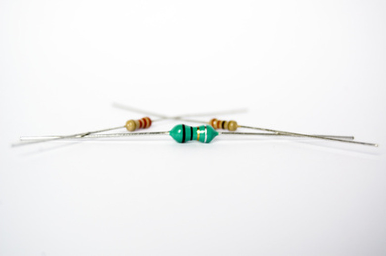
Twist together the first lead on the 500 ohm resistors to the free end of the first wire. Twist together the free end of the second wire to the free lead on the 500 ohm resistor.
Step 3
Turn on the multimeter and set the scale to "Volts DC." Measure the voltage across the 500 ohm resistor; it should be approximately 6VDC.
Step 4
Turn the multimeter scale to "Resistance" and measure the 1 kiloohm resistor. Verify that the resistor measures within 10 percent of 1 kiloohm. Disconnect the multimeter and switch the scale setting to "Volts DC."
Step 5
Twist the first 1 kiloohm resistor lead together with the first 500 ohm resistor lead. Twist together the second 1 kiloohm resistor lead together with the second 500 ohm resistor lead. Measure the voltage across the 1 kiloohm resistor; it should be approximately 6VDC.
Step 6
Calculate the current flowing through the 1 kiloohm "load" resistor using the following formula:
Voltage / Resistance = Current
Things Needed
- Digital multimeter
- One 1 kiloohm resistor
- One 500 ohm resistor
- One 6V battery
- Electrical wire
- Electrical pliers
TL;DR (Too Long; Didn't Read)
To verify your calculation, switch the multimeter scale to "Current" and disconnect the first 1 kiloohm lead from the circuit. Attach one of the multimeter probes to the first lead on the 500 ohm resistor, and attach the other multimeter probe to the detached 1 kiloohm resistor lead. Check the multimeter reading to verify the current value.
References
- "Principles of Electric Circuits"; Thomas Floyd; 1997
- Georgia State University: DC Power in Series and Parallel Circuits
Cite This Article
MLA
Sandoval, David. "How To Calculate Load Current" sciencing.com, https://www.sciencing.com/calculate-load-current-6404892/. 24 April 2017.
APA
Sandoval, David. (2017, April 24). How To Calculate Load Current. sciencing.com. Retrieved from https://www.sciencing.com/calculate-load-current-6404892/
Chicago
Sandoval, David. How To Calculate Load Current last modified March 24, 2022. https://www.sciencing.com/calculate-load-current-6404892/
