How To Check A Parallel Circuit
Parallel circuits are formed when electrical components are wired together so that they are all connected to the same point. They all share the same voltage, but divide the current. The total amount of current in the circuit remains the same.
Parallel circuits are useful because when one component fails, the others will not be affected. This type of wiring is found in Christmas lights and household wiring systems. To check parallel circuits, use a digital multimeter to find the resistance and voltage of the components. The current may be checked as an option. Calculate theoretical values with Ohm's Law. Ohm's Law is V = IR, where I is the current and R is the resistance. To find the total resistance for a parallel circuit, calculate 1/R(Total) = 1/R1 + 1/R2 + ...+ 1/R(Last). Practice these methods with resistors connected in parallel.
Step 1
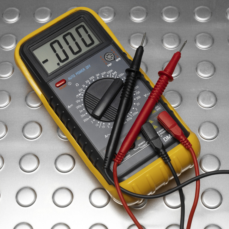
Measure the resistance of each resistor. Switch the multimeter on and turn its knob to the resistance setting, which is labeled with the Greek letter Omega. Hold a multimeter probe against each resistor lead, and record the results.
Step 2
Add the battery holder to the circuit. Do this by placing its red lead into a hole that is next to the red stripe at the top of the breadboard. Add the black wire into one of the holes alongside the row that is next to the blue stripe. Label the blue stripe row ground. If the breadboard does not have stripes, use one column for the red wire, and a separate column for the black one.
Step 3
Insert the 100-ohm resistor into the breadboard so that it is vertical. Place the 220-ohm resistor parallel to it, and then add the 330-ohm resistor so that is parallel to the other two.
Step 4
Place a jumper wire between the column at the bottom of the 100-ohm resistor and the row that the battery holder's red wire is in. Place another jumper between the top part of the 100-ohm resistor and the row that the blue wire is in. Repeat the procedure for the other two resistors. The bottom parts of the resistors now share the same point, and so do the top parts.
Step 5
Measure the voltage across each resistor. Do this by placing the multimeter on a DC volt setting, then holding one probe against each of the resistor's leads. Record the results.
Step 6
Measure the current in the 100-ohm resistor. To do this, place the multimeter on a milliamp or mA current setting. Move the red probe from the voltmeter opening on the multimeter casing to the ampere opening. Insert one end of a jumper into the row next to the red stripe on the breadboard, and use an alligator clip to attach the multimeter's red probe to its free end. Disconnect the front end of the wire connecting the back part of the 100-ohm resistor to this row, leaving its other end connected to the breadboard. Place the black probe against this wire, and record the current. Insert the resistor's connecting wire back into the breadboard. Leave the red probe attached to the extra jumper wire.
Step 7
Measure and record the current for the 220-ohm resistor by removing the front end of the jumper connecting it to the breadboard, and placing the black probe against it. Use the same procedure for the 330-ohm resistor, each time making sure to put the wires back into position when the measurement is finished. Remove the extra jumper wire from the breadboard, and detach it from the multimeter's red probe. Place the red probe back into the voltage setting in the casing.
Step 8
Calculate the total theoretical resistance of the three resistors in parallel. The equation is 1/R(Total) = 1/R1 + 1/R2 + 1/R3. Substituting values of R1 = 100, R2 = 220, and R3 = 330 gives 1/R(Total) = 1/100 + 1/220 + 1/330 = 0.010. + 0.0045 + 0.003. Therefore 1/R(Total) = 0.0175 ohms and R(Total) = 57 ohms.
Step 9
Calculate the theoretical current I for each resistor. The equation is I = V / R. For the 100-ohm resistor, it is I1 = V / R1 = 3 V / 100 = 0.03 amps = 30 mA. Use the same procedure for the other two resistors. The answers are I2 = 3 V / 220 = 13 mA, and I3 = 3 V / 330 ohm = 9 mA. Compare these calculated results with the experimental results found when the multimeter was used to measure the current.
Things Needed
- 100-ohm resistor
- 220-ohm resistor
- 330-ohm resistor
- 2 AA batteries
- Battery holder
- Jumper wires
- Solderless breadboard
- Digital multimeter
Warning
To avoid blown fuses, follow the instructions carefully when using the multimeter to measure current.
References
- "Conceptual Physics"; Paul Hewitt; 2006
- "University Physics"; Richard Wolfson; 2007
Cite This Article
MLA
Lewis, Kim. "How To Check A Parallel Circuit" sciencing.com, https://www.sciencing.com/check-parallel-circuit-8781567/. 24 April 2017.
APA
Lewis, Kim. (2017, April 24). How To Check A Parallel Circuit. sciencing.com. Retrieved from https://www.sciencing.com/check-parallel-circuit-8781567/
Chicago
Lewis, Kim. How To Check A Parallel Circuit last modified March 24, 2022. https://www.sciencing.com/check-parallel-circuit-8781567/