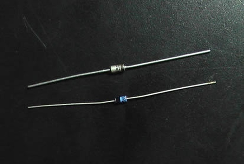
How To Check A Zener Diode
A Zener diode is a diode designed to operate in the breakdown region. These conditions destroy normal diodes, but a Zener conducts a small amount of current. It maintains a constant voltage across the device, so it is typically employed as a simple voltage regulator in many circuits. To check one, use a multimeter to test its voltage both in and out of circuit.
A 1N4734A Zener diode has a 5.6-volt and a 1 W power rating. It supplies a stable 5.6 volts to a circuit. The maximum current is approximately 1 W/ 5.6 V = 179 mA. To prevent excessive current in a test circuit, use a 200-ohm resistor in series with the diode.
Step 1
Placing the multimeter on the diode setting. This is usually indicated by a small diode symbol on the casing.
Step 2
Measure the forward voltage drop across the Zener diode. Do this by connecting the multimeter's positive or red lead on the anode side of the diode, which is unmarked. Place the negative or black lead on the cathode side of the diode, which is marked by a stripe. A Zener is made from silicon, so an undamaged device reads 0.5 to 0.7 V when it is forward-biased.
Step 3
Measure the reverse-biased voltage on the Zener diode by switching the multimeter probes. Place the positive lead on the marked or cathode side, and the negative lead on the unmarked or anode side. You should get a reading indicating infinite resistance or no current flow.
Step 4
Attach the positive side of the 9-V battery to one side of the resistor and connect the other end of the resistor to the cathode side of the Zener diode, so that it will be reverse-biased. Then wire the remaining diode terminal to the negative side of the battery.
Step 5
Place the multimeter on a DC voltage setting. Measure the voltage across the diode by placing a multimeter lead on each terminal. It should read approximately 5.6 volts, though the value may be as low as 5.32 or as high as 5.88 volts. Note that the voltage between the battery and ground remains at 9 V.
Things Needed
- Multimeter
- 1N4734A or equivalent Zener diode
- 9-volt battery
- Connecting wire
- 200-ohm resistor
- 1N4734A data sheet
TL;DR (Too Long; Didn't Read)
Resistors may be off as much as 20 percent of their rated value. Use a precision one if you need more accuracy. These calculations do not take into account the Zener resistance, which is important for precise measurements.
Warning
The Zener must be reverse-biased, or else it will behave like a regular silicon diode. Diodes are sensitive devices. Be sure not to exceed the power, current, and temperature ratings specified by the manufacturer. Always exercise caution when building electrical circuits to avoid burning yourself or damaging your equipment.
References
- "Electronic Principles;" Albert Malvino; 1999
- "Getting Started in Electronics;" Forrest Mims III; 2000
- "The Art of Electronics;" Paul Horowitz and Winfield Hill; 1997
- Georgia State University: Zener Diode
Cite This Article
MLA
Lewis, Kim. "How To Check A Zener Diode" sciencing.com, https://www.sciencing.com/check-zener-diode-5724083/. 24 April 2017.
APA
Lewis, Kim. (2017, April 24). How To Check A Zener Diode. sciencing.com. Retrieved from https://www.sciencing.com/check-zener-diode-5724083/
Chicago
Lewis, Kim. How To Check A Zener Diode last modified March 24, 2022. https://www.sciencing.com/check-zener-diode-5724083/
