Coil Winding Basics
Electrical engineers perform coil winding to use coils as parts of electric circuits and for use in devices such as toroidal cores that are involved with magnetic fields and magnetic force. The shape and methods used to wind coils can let them be used for different purposes.
The different ways of winding coil means you can wind coils for specific uses by taking into account voltage of the electrical current driven through the coils and the heat insulation properties of the devices themselves.
For electromagnets, materials that become magnetic in the presence of electric current flowing through wires, coils should be wound such that windings that are next to one another travel in opposite directions. This prevents the current that flows through them from canceling itself out between the layers of coils.
The ways engineers select the winding structure and methods of winding depend on the design choices such as the space available for winding when designing coils or the location of the final part of the coil that's meant to be wound.
Coil Winding Machines and Methods
Coil Winding Machines and Methods
If you wanted to wind a coil by hand or do it as haphazardly as possible without respect to the optimal physics and mathematics underneath, this method is called wild winding or jumble winding.
Jumble winding involves winding randomly without being conscientious of layer or filling in depths appropriately. It's quick, easy, and gets the job done, but it doesn't change the inductance of the wound wire setup to produce an optimal voltage. It's used in small transformers, ignition coils, small electrical motors, and devices with small wire gauges.
When winding coils through jumble winding, engineers also take into account the winding height as measured by
\(h=\frac{d^2n}{b}\)
with:
- d as the wire gauge length,
- n as the number of windings,
- b as the width of winding.
Machines that opt to wind coils helically (spiral) in every layer are helical winding machines. As these machines create layers and layers of coil, they switch between directions, moving forward and backward (or left-handed and right-handed, as engineers use to refer to those directions). This only works for a small number of layers because when it reaches a certain limit, the structure becomes too tight to contain and jumble winding may result.
Orthocyclic winding is the most optimal method to wind circular cross-sectional coils by placing the wires in the upper layers in the grooves of wires in the lower layers. These coils have good heat conduction and regularly distribute the field strength well among themselves.
Orthocyclic winding
Orthocyclic winding
Engineers take into account the efficiency of their coil winding processes by minimizing the materials and space required for coil winding. They do this to ensure they spend energy in an optimal manner. The electrical conductors used in coil winding occupy an area, and so does the winding used in the process. The fill factor is the ratio of these two areas and can be calculated as
\(F=\frac{d^2n\pi bh}{4}\)
with:
- wire gauge length d,
- number of windings n,
- and bh as the base and height of the coil body that gives the cross section as an area.
Engineers try to achieve as high fill factors as possible to make the coil winding process as efficient as it can be. Though engineers generally calculate a theoretical fill factor of .91 for orthocyclic winding, the wire insulation means that, in practice, the fill factor is lower.
When winding coils through orthocyclic winding, engineers measure winding height a
\(h=(1+(n-1)\sin{60^{\text{o}}})d\)
with:
- n as the number of layers
- d as the maximum wire gauge length.
This accounts for the angles of the spaces between the wires and layers of wires from the cross-sectional point of view.
Densely Packed Wire
Densely Packed Wire
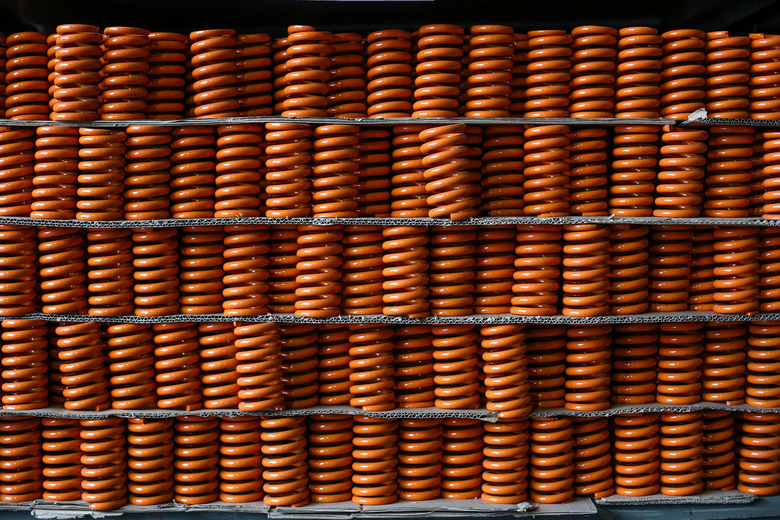
The more densely packed wires are the higher the fill factor, as the coil winding machine can use the heat conductivity of the winding to prevent heat loss. Orthocyclic winding, the optimal method of arranging circular cross-sectional coils, lets engineers achieve a fill factor of about 90% this way.
Through this method, round wires in the upper layer of a coil winding machine should be packed such that they are in the grooves of the wires in the lower layer to ensure the packaging can encompass as many wires as possible. The side view of the coils arranged in this manner show how different layers arrange themselves in the most efficient manner possible.
Winding should run parallel to the winding flanges, the supports used to make sure coils wind as tight and efficiently as possible. Engineers should adjust the winding width to the number of turns per layer of the winding. If the cross-sectional areas of these wires are non-circular, the crossover area between the wires needs to be on the small side of the coil body.
Engineers decide the winding structure based on the needs and purposes of the coil itself. Finally, coil wires can be shaped into rectangular or flat cross sectional shapes such that there are no air gaps between them as an even more optimal winding method for an even greater fill factor.
Manufacturing Orthocyclic Windings
Manufacturing Orthocyclic Windings
To create and operate machines that can manufacture orthocyclic windings with such precision and care means that engineers have to address some problems. Often, engineers and researchers can run into issues with how the the coil winding machines wind at such high speeds.
Wires in practice are also not as straight as they are in theoretical calculations and models and, instead, the volume and mass of the wire itself makes the coil winding process even more difficult. Any sort of bend, anomaly in uniformity or shape or any other feature that the equations of optimal coil winding structures don't account for will offset the production of an entire coil.
When a coil is being wound up through the windings of the coil machine, even the material that's used on the surface of the coils themselves add a thickness to the diameter of the circular cross-sectional ares of the coils, and the material on the surface of these coils affect the coil winding process.
The coating can cause wires to slide against one another, expand or contract due to changes in temperature, change in stiffness or durability and even elongate a certain amount as a result of all of these forces. This makes it more difficult for engineers to determine the appropriate wire gradient and how that changes with respect to the wire diameter.
Orthocyclic Coil Rewinding Service
Orthocyclic Coil Rewinding Service
Though orthocyclic winding may seem like the optimal method, engineers need to address issues when putting ideas into practice. With the parameters specified to control the number and design of the coil windings, coil winding machines use an iterative approach to estimate the cross section and space available for insulated coil. The iterative approach accounts for deformities and changes in shape at each step after adding each layer, one by one.
Engineers can address these issues by making sure that every single part of a winding wire of the first layer fits into a certain position that the machine has already calculated. The coil winding machines can use the groove geometry to determine how the subsequent layers fit into the space available through approximations. The machine measures the locations to appropriately place each wire layer by accounting for the changes in the shape of the coil by taking into account the forces the issues raise.
This iterative process create wires that have exceptional load for certain uses such as pulleys. They can apply the appropriate grooves to the winding to fit the shape of the device, especially in cases in which the deformation of the wire is unavoidable.
Bike Coil Rewinding
Bike Coil Rewinding
Similar to coil winding machines, you can rewind the stator of a bicycle through a series of steps. Bicycles use stators as steel drums to protect the inner workings of an electric motor. They use the magnetism of wires to power their processes.
You will need a knife, a screwdriver, steel wool, a cloth, copper wire, terminal leads, a multimeter or an ohmmeter and liquid rubber.
1. Make sure each individual coil head on the stator has normal wires. You need to cut the rubber coating on damaged or burned wires that have black marks. 2. Examine the wire's direction around the coil head to figure out what the terminal clips are attached to. Remove the terminal clips from the damaged wires using a screwdriver. 3. Unwind the damaged wire from the stator and clean the surface with a lint-free cloth. 4. Wind the new copper wire as a coil using the same gauge as the wire already on the stator. Coil it tight to remove spaces or gaps between the wires. Make sure to leave 1-inch lengths of the wire at the top and bottom of each head for the new terminals. 5. Use pliers to squeeze together the new terminal leads to the copper wire. Use a screwdriver to attach the terminal leads to the stator. 6. Use a multimeter or ohmmeter to measure the resistance main leads of the stator to make sure that they're connected properly. Connect the black meter probe to either of the main leads and the red meter probe to the remaining part of the stator. Any resistance reading indicates the wire setup is working. 7. Use liquid rubber to coat the new wires for protection.
Different Winding Processes
Different Winding Processes
Linear winding method
The linear winding method of coil winding creates windings onto rotating coil bodies or coil-carrying devices. By forcing the wire through a guiding tube, engineers can mount the wire onto a post or a clamping devices to remain secure.
The wire guiding tube then lays down each layer of the wire so that it's wound such that the wire distributes itself through the winding space of the coil body. The guiding tube moves the coil in to account for the differences in wire diameters sometimes with rotational speed frequencies of up to 500 s-1 with speeds of 30 m/s.
Flyer winding method
Flyer winding or spindle winding uses a nozzle that attaches wires to a flyer, a rotating device at a distance from the coil. The flyer shaft fixes the winding component in the winding area so that the wire fixes itself outside of the flyer. Wire clips or deflections pull along and fixate the wire so that the components change quickly between one another. These devices let the different components of the wire with clips that fix to the machine.
With the rotational coil stationary, the wires are rotated and layered around it using high-powered rotors. The rotors are made up of metal sheets so that the flyer isn't guided directly, but, instead, the wire is guided across guiding blocks for grooves or slots of the location it's meant to be.
Needle winding method
Machines that use needle winding wind the wires using a needle with a nozzle at a right angle to the direction of the wire's movement. The nozzle then lifts itself for each groove in the layer of the coil. The process then reverses itself to add coils in the other direction. This lets engineers attain the precise layer structures.
Toroidal winding method
To create a toroid of wires around a circular ring, the toroidal winding method mounts the toroidal core around which a wires are coiled. As the toroid rotates, the machine winds the wires around. The wire coiling mechanism distributes the wire around until the toroid is fully wired. Though this method has a high manufacturing costs, they tend to give a low strength loss due to magnetic flux and result in favorable power densities.
Cite This Article
MLA
Ather, S. Hussain. "Coil Winding Basics" sciencing.com, https://www.sciencing.com/coil-winding-basics-7480758/. 27 December 2020.
APA
Ather, S. Hussain. (2020, December 27). Coil Winding Basics. sciencing.com. Retrieved from https://www.sciencing.com/coil-winding-basics-7480758/
Chicago
Ather, S. Hussain. Coil Winding Basics last modified August 30, 2022. https://www.sciencing.com/coil-winding-basics-7480758/