How To Design A Centrifugal Pump
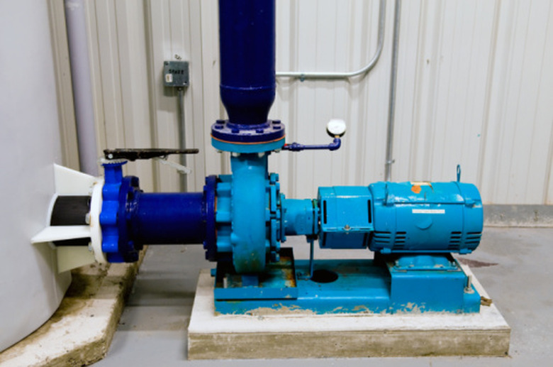
A centrifugal pump works by converting the energy of a spinning impeller to increase the velocity of a liquid. The impeller is the device that rotates in the liquid and is usually contained inside a volute, or casing. The impeller is typically connected to an electric motor which provides the energy to be transferred to the liquid. The pump must be designed to carry the desired flow rate, using the most efficient and properly sized motor.
Step 1
Determine the specific gravity of the liquid to be pumped. For water close to 65 degrees Fahrenheit and typical domestic sanitary sewage, the liquid is assumed to have a specific gravity of 1.0.
Step 2
Determine the vertical distance from the center of the pump volute to the outlet of the discharge pipe. This is the lift of the pump and will be measured in feet.
Step 3
Determine if there is going to be any pressure at the discharge point. This pressure, measured in pounds per square inch (PSI), must be overcome by the pump in order to move the liquid. The pressure could be due to pressure in the pipe the discharge pipe is connected to, or it could be the pressure due to the discharge point being submerged in liquid. If the pipe is submerged, the discharge pressure will be simply the maximum depth of submergence in feet. This is called the discharge pressure head.
Step 4
Note whether the discharge point is another pipe under pressure. If so, the discharge pressure head is converted to feet of head by dividing the pressure in PSI by the specific gravity of the liquid, then multiplying that answer by 144, then dividing again by 62.4. This will give an answer in feet of head. The total discharge head is the pump lift plus the discharge pressure head.
Step 5
Determine the head on the suction side of the pump. If the pump is drawing from a pipe under pressure, convert the pressure to feet of head. Otherwise, the suction head is the distance from the free liquid level to the center of the pump volute.
Step 6
Subtract the suction head from the discharge head to determine the total Static Head of the pump.
Step 7
Determine the dynamic head by using the design flow of the pump. The design flow will cause pressure on the pump due to the friction of the discharge pipe. The head due to friction, or friction loss, can be determined with the use of tables constructed for this purpose by pipe manufacturers. The friction loss is given in feet of head — usually per 1000 feet of pipe.
Step 8
Determine the best pipe diameter by knowing the length of the discharge piping and the number of fittings. Usually the best pipe diameter is the one with the least friction but that still maintains a minimum velocity in the pipe. The maximum velocity in the pipe should also be checked to ensure that it is within design parameters.
Step 9
Add all the fittings and the pipe length to compute the total friction loss in feet of head — this will be the Friction Head. Each pipe fitting is equivalent to a certain length of pipe.
Step 10
Determine the type of centrifugal pump needed. As pump manufacturers build pumps for particular purposes, the characteristic of the impeller and volute change depending on what is being pumped and the desired flow velocity. A typical water supply pump design would choose a high-speed pump. A pump for dewatering excavations with silt and sand would be a mud pump constructed for the purpose. There are also pumps specifically for moving sanitary sewerage.
Step 11
Add the Static Head to the Friction Head to determine the total Dynamic Head. Use the Dynamic Head and the desired flow rate to size the pump. Centrifugal pumps are sized by choosing an impeller diameter, inlet diameter and pump motor horsepower. The inlet diameter is usually the same size or smaller than the discharge pipe.
Step 12
Use the diameter of the inlet of the pump to select which pump impeller and motor curve to use. Each manufacturer of pumps publishes pump curves which plot the flow rate versus the pump head for each impeller that can be used on the chosen pump.
Step 13
Find the point on the pump curves that is the intersection of the Dynamic Head and the Discharge Rate. If the pump can be used, there should be a curve on the chart above and to the right of this point labeled with an impeller size. This will be the design impeller diameter. This point will also be inside a curve representing the efficiency of the motor that is being used on the pump. Look for the highest efficiency possible. Most curves are plotted for 65 degree Fahrenheit water as the liquid. Correct the pump motor size for different liquid densities.
Step 14
Check several pump motors and impeller curves to find the most efficient one for your purposes. This will be your selected pump.
Things Needed
- Calculator
- Pump curves
TL;DR (Too Long; Didn't Read)
The larger the impeller diameter, the greater the pump flow.
A pump and impeller will have the same flow rate regardless of the liquid density as long as the liquid has very little viscosity. However, the power required from the motor will change.
Warning
If the pump is located above the liquid it is drawing from, you must check the suction head to be sure that the liquid does not cause pump cavitation and failure. Consult the manufacturer's documentation to determine this.
Cite This Article
MLA
Colbath, Steven. "How To Design A Centrifugal Pump" sciencing.com, https://www.sciencing.com/design-centrifugal-pump-7995990/. 24 April 2017.
APA
Colbath, Steven. (2017, April 24). How To Design A Centrifugal Pump. sciencing.com. Retrieved from https://www.sciencing.com/design-centrifugal-pump-7995990/
Chicago
Colbath, Steven. How To Design A Centrifugal Pump last modified March 24, 2022. https://www.sciencing.com/design-centrifugal-pump-7995990/
