How To Determine The Sag In Transmission Lines
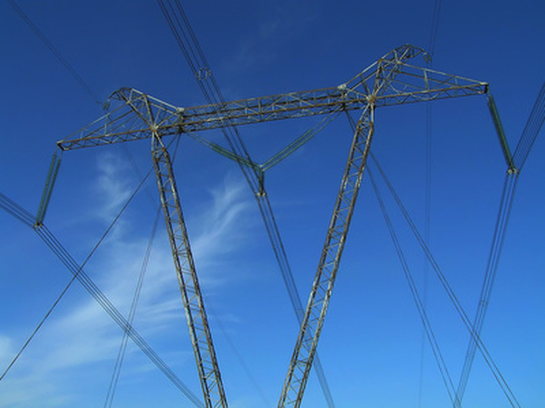
When you find yourself looking at an endless line of tall electrical towers carrying power wires as far as the eye can see, the first thing that comes to your mind is probably not "Look at those sagging transmission lines." Yet the way that the wires curve down between the towers is as much a characteristic of this type of electricity conduit as the towers themselves.
While ordinary electric wires in your neighborhood are connected in nearly straight lines to adjacent poles, the much greater distance between more remote high-voltage transmission wires, as well as the weight of those wires, rules out this arrangement. As a result, they must be allowed to sag in between or risk breaking owing to extreme tension. On the other hand, an excessive sag allowance is costly to the power company in that too much sag uses more material in the form of extra wire.
Calculating the sag between lines and finding an optimal value is straightforward enough mathematical exercise.
The Geometry of Sagging Wires
The Geometry of Sagging Wires
Let L be the horizontal distance between adjacent towers (assumed to be the same height, often not a valid assumption in reality), W be the weight per unit length of conductor in N/m, and T the tension in the conductor, for force per unit length in N/m. O is the point of lowest sag, midway between the towers.
Choose some point P along the wire. If you choose O as the (0,0) point of a standard coordinate system, the coordinates of point P are (x,y). The weight of the length of the curved wire segment OP = Wx and acts (x/2) meters from O, since the wire's mass is equally distributed about this midpoint. Because this section is in equilibrium (otherwise it would be moving), no net torques (forces that act to rotate bodies) are acting on the wire.
Balancing Forces: Weight and Tension
Balancing Forces: Weight and Tension
The torque resulting from the tension T therefore equals the tension owing to the line weight Wx:
\(Ty = Wx(x/2)\)
where y is the vertical distance from O to whatever height P occupies. This is found by rearranging the equation:
\(y = Wx^2/2T\)
To calculate the total sag, set x equal to L/2, which makes y equal to the distance from the top of either tower – that is, the sag value:
\(sag = WL^2/8T\)
**Example:** The tops of equally tall adjacent transmission towers wires are 200 m apart. The conducting wire weighs 12 N/m, and the tension is 1,500 N/m. What is the sag value?
With W = 12 N/m, _L2_ = (200 m)2 = 40,000 m2 and T = 1,500 N/m,
sag = [(12)(40,000)]/[(8)(1,500)] = 480,000/12,000 = 40 m
Effects of Wind and Ice
Effects of Wind and Ice
Transmission wires would be much easier to build and maintain were it not for the pesky phenomenon of weather, in particular ice and wind. Both of these can physically damage just about anything, and transmission wires are often especially susceptible owing to their exposure in open spaces high above the ground.
Changes to the above equation to account for this are made by incorporating _wi_, the weight of ice per unit length, and _ww_, the wind force per unit length, directed perpendicular to the the direction of the wires. The total effective weight of the wire per unit length becomes:
\(w_{t} = \sqrt{(w + w_{i})^2 + (w_{w})^2}\)
The sag value is then calculated as before, except that wt is substituted for W in the equation for determining sag in the absence of external forces other than gravity.
Cite This Article
MLA
Beck, Kevin. "How To Determine The Sag In Transmission Lines" sciencing.com, https://www.sciencing.com/determine-sag-transmission-lines-7917037/. 13 December 2019.
APA
Beck, Kevin. (2019, December 13). How To Determine The Sag In Transmission Lines. sciencing.com. Retrieved from https://www.sciencing.com/determine-sag-transmission-lines-7917037/
Chicago
Beck, Kevin. How To Determine The Sag In Transmission Lines last modified March 24, 2022. https://www.sciencing.com/determine-sag-transmission-lines-7917037/
