Electric Circuit: Definition, Types, Components (W/ Examples & Diagrams)
The electrical wiring in your home that keeps your laptop, phone charger, and lesser tools such as refrigerators and stoves humming along consists of a number of interconnected electrical circuits. These are connected to whatever power source supplies electricity to your home.
The purpose of circuits is to get electricity and its considerable energy potential exactly where it needs to go, and to contain the potentially harmful effects of electricity in the process.
What's going on inside all those wires, which themselves are mostly out of your sight? To start with the basics, free electrons will move in the presence of an electric field, for physical reasons that will be described later. If they are given a closed-loop path in which to flow, an electrical circuit can be created.
A simple circuit consists only of a source of voltage (electrical potential difference); a medium through which electrons can flow, usually a wire; and some source of electrical resistance in the circuit. Most real-world examples are far more complex, however, and multiple types of electrical circuits exist, all of which are vital to the efficient flow of electricity.
Electric Charge and Current
Electric Charge and Current
The basic conceptual elements in the world of electricity are current, voltage and resistance. Before exploring these, it's necessary to look a little deeper, back to the idea of free electrons. An electron by convention carries a negative charge with a magnitude of 1.60 × 10⁻¹⁹ coulombs, or C. Since it is the flow of electrons that determines current, charges in a circuit flow away from the negative terminal and in the direction of the positive terminal.
The "unit charge" in physics is standardized as positive and has the same magnitude as the charge e on an electron. A positive charge placed near a positive terminal will experience "repulsion," and "want" to move away from the terminal, all the more strongly as the distance closes to zero. In this state, the charge has a higher electric potential than it does at some distance farther away.
Thus a "charge" ("positive" being implied unless stated otherwise) flows from areas of higher voltage to areas lower voltage. This is the potential difference or voltage referred to in physics, and its magnitude in part determines current flow in a circuit. Electric current comes in alternating current (a "jittery," phasic flow) and direct current (uniform flow) forms; the latter is the modern standard in use in electrical power grids.
- Current flow is measured using a device called an ammeter. The same device can usually be used as a voltmeter to measure potential difference.
Ohm's Law
Ohm's Law
The previous section can be largely summarized by a simple mathematical law called Ohm's law:
\(I=\frac{V}{R}\)
where I is current in amperes (C/s), V is voltage, or potential difference, in volts (joules per C, or J/C; note the energy term in the denominator) and R is the resistance in ohms (Ω).
In a series circuit, the resistances of individual resistors are added together to calculate the resistance of the circuit as a whole. In parallel circuits, which you'll read about soon, the rule is:
\(\frac{1}{R_{tot}}=\frac{1}{R_1}+\frac{1}{R_2}+...+\frac{1}{R_n}\)
where _R1, R2_ and so on are the individual values of the n resistors in the parallel circuit.
Definition of a Circuit
Definition of a Circuit
A circuit is a closed loop through which electric charge flows as a result of a driving voltage. Current is the rate of flow, measured as the amount of charge passing a given point in the circuit per unit time.
Sometimes it is helpful to think of current in a wire circuit as analogous to water flowing through pipes. Water will flow from regions of high potential energy to regions of lower potential energy. Some source would need to then use energy to raise the water up so that it will flow downhill. In order to have a continuous flow of water, once the water reaches the bottom, it must be lifted back up to the top. **This action of lifting the water back up to the top is essentially what a battery or power source does in an electric circuit.**
The goal of a circuit is to do something useful with this flow of charge. All circuits include some sort of resistive element that slows the flow of charge, just as a dam slows the flow of water from a reservoir. If a light bulb is added to a circuit, for example, it slows the flow of charge and transforms the associated energy into light.
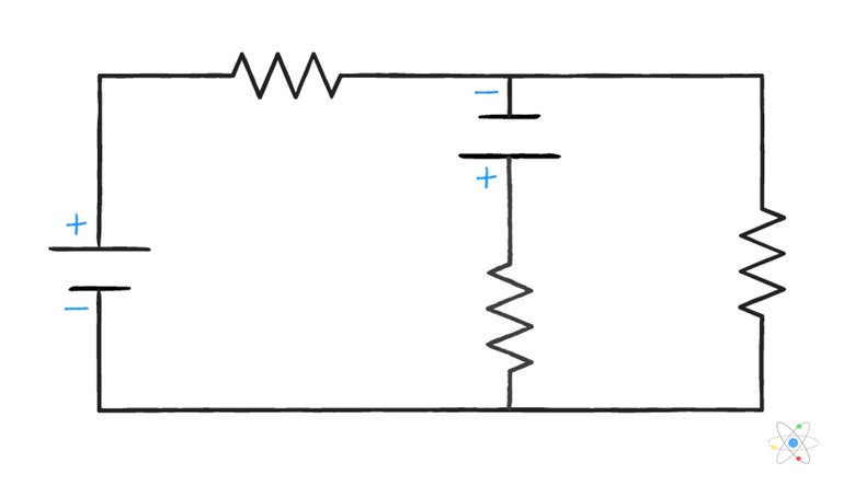
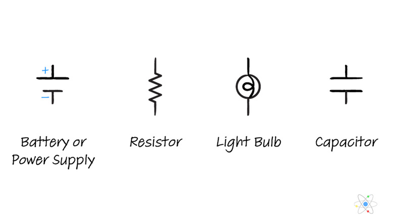
Circuit Diagrams and Circuit Elements
Circuit Diagrams and Circuit Elements
Often it is useful to sketch a diagram of a circuit if you are given some combination of V, I and R and asked to solve for the unknown quantity. To do so, use a set of symbols to simplify the sketch.
 Dana Chen | Sciencing
These symbols are then connected with straight lines to create a circuit diagram.
Dana Chen | Sciencing
Types of Circuits
Types of Circuits
A series circuit has elements connected in series, or one after the other without the wire branching. The current flowing through all elements connected in series is the same, no matter how many resistors are encountered along the way.
A parallel circuit has elements connected in parallel – that is, one point in the circuit branches, with wires going to two different elements, and then the branches rejoin again. **The voltage across each element connected in parallel is the same.**
An open circuit is one in which no current can flow because the loop is broken at some point. A closed circuit is one in which the complete loop is formed and current can flow. Clearly, the latter tends to be more interesting to study.
A short circuit is one in which the resistive elements are bypassed and current flow is very high. These are generally undesirable, and devices called circuit breakers are installed in circuits to "break" (open) the circuit and halt current flow to protect against damage to the circuit and electrical appliances, and to protect against fires.
Electric Circuit Examples
Electric Circuit Examples
1\. A series circuit includes a 9-V power source (a battery, in this case) and four resistors with resistance values of 1.5, 4.5, 2 and 1 Ω. What is the current flow?
First, calculate the total resistance. Recalling the rule given in a previous section, this is simply 1.5 + 4.5 + 2 + 1 = 9 Ω. Thus the current flow is
\(I=\frac{V}{R_{tot}}=\frac{9}{9}=1\text{ A}\)
2\. Now imagine the same voltage and four resistors, but with the 1.5-Ω and 4.5-Ω resistors placed in parallel and the others arranged the same as before. What is the current flow?
This time, calculate the resistance in the parallel part of the circuit. This is given by 1/R = 1/1.5 + 1/4.5 = 8/9 = 0.89. **Don't forget to take the reciprocal of this number to get R!** This is given by 1/0.89 = 1.13 Ω.
You can now treat this portion of the circuit as a single resistive element with a resistance of 0.89 Ω, and the entire problem is solved as with a series circuit: Rtot = 1.125 + 2 + 1 = 4.13 Ω. This allows you to solve for current once more: _V/Rtot_ = 9 V/4.13 Ω = 2.18 A.
3\. Finally, building on the set-up in previous example, combine the 2-Ω and 1-Ω resistors in a parallel circuit, yielding two sets of parallel circuits that are themselves arranged in series. What is the current flow now?
Solve for the resistance of the new parallel circuit: 1/R = 1/1 + 1/2 = 1.5; R = 2/3 = 0.67 Ω. The total resistance is thus 1.13 + 0.67 = 1.79 Ω. The current in the again-revamped circuit is thus 9 V/1.79 Ω = 5.03 A.
These examples illustrate that distributing resistance across parallel resistors increases the amount of current flowing by lowering the total resistance, since voltage doesn't change.
Cite This Article
MLA
Beck, Kevin. "Electric Circuit: Definition, Types, Components (W/ Examples & Diagrams)" sciencing.com, https://www.sciencing.com/electric-circuit-definition-types-components-w-examples-diagrams-13721178/. 28 December 2020.
APA
Beck, Kevin. (2020, December 28). Electric Circuit: Definition, Types, Components (W/ Examples & Diagrams). sciencing.com. Retrieved from https://www.sciencing.com/electric-circuit-definition-types-components-w-examples-diagrams-13721178/
Chicago
Beck, Kevin. Electric Circuit: Definition, Types, Components (W/ Examples & Diagrams) last modified March 24, 2022. https://www.sciencing.com/electric-circuit-definition-types-components-w-examples-diagrams-13721178/