What Are The Functions Of A Current Transformer?
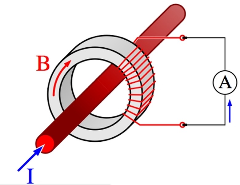
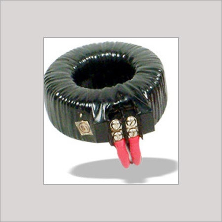
A current transformer (CT) is a transformer which measures the current of another circuit. It is coupled to an ammeter (A in the diagram) in its own circuit to perform this measurement. Measuring high-voltage current directly would require insertion of measuring instrumentation into the measured circuit–an unnecessary difficulty which would draw down the very current meant to be measured. Also, the heat generated in the measuring equipment from the high current could give false readings. Measuring current indirectly with a CT is much more practical.
Voltage and Current Transformer Relationships
Voltage and Current Transformer Relationships
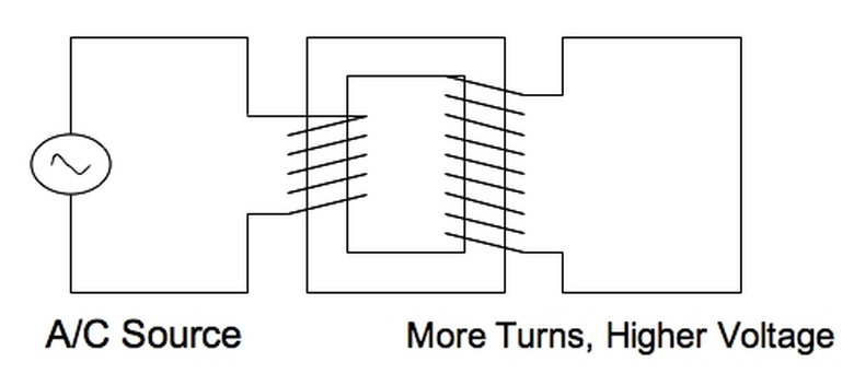
The function of a current transformer (CT) can be understood better by comparing it to the more commonly known voltage transformer (VT). Recall that in a voltage transformer, an alternating current in one circuit sets up an alternating magnetic field in a coil in the circuit. The coil is wrapped around an iron core, which spreads the magnetic field, nearly undiminished, to another coil in a different circuit, one without a power source.
In contrast, the CT's difference is that the circuit with power has, effectively, one loop. The powered circuit goes through the iron core only once. A CT is, therefore, a step-up transformer.
CT & VT Formulae
CT & VT Formulae
Recall also that the current and number of turns in the coils in a VT can be related as:
\(i_1N_1=i_2N_2\)
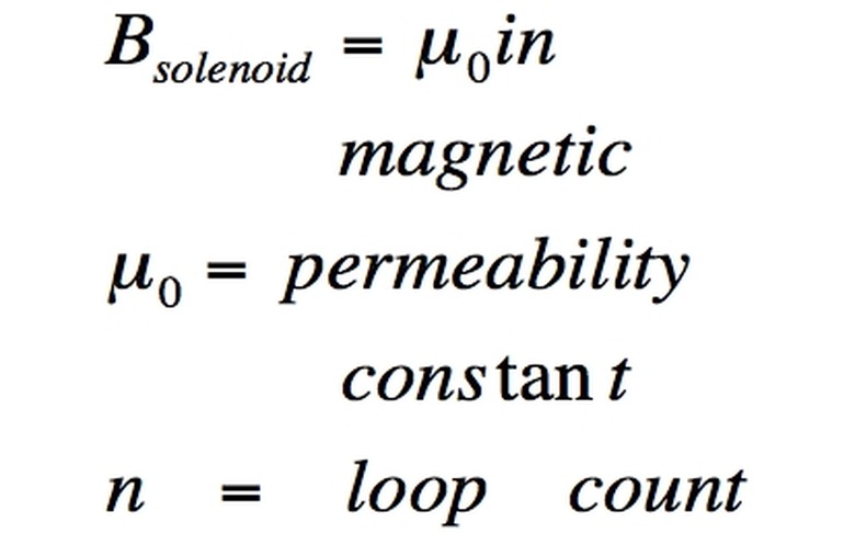
This is because for a coil (solenoid):
\(B=\mu Ni\)
where mu here means the magnetic permeability constant. Little intensity of B is lost from one coil to the other with a good iron core, so the B equations for the two coils are effectively equal, giving us the first relationship.
However, N1 = 1 for the primary in the case of the current transformer. Is the single power line effectively the equivalent of one loop? Does the last equation reduce to i1 = i2 N2? No, because it was based on solenoid equations. For N1 = 1, the following formula is more appropriate:
\(B=\frac{\mu i}{2\pi r}\)
where r is the distance of the center of the wire to the point where B is measured or sensed (the iron core, in the transformer case). So:
\(\frac{i}{2\pi r}=i_2N_2\)
i1 is, therefore, merely proportional to the ammeter-measured value i2, reducing current measurement to a simple conversion.
Common Transformer Uses
Common Transformer Uses
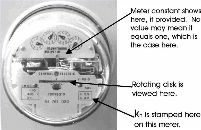
The one central function of a CT is to determine the current in a circuit. This is especially useful for monitoring high-voltage lines throughout the power grid. Another ubiquitous use of CTs is in domestic electric meters. A CT is coupled with a meter to measure what electrical usage to charge the customer.
Electrical Instrument Safety
Electrical Instrument Safety
Another function of CTs is protection of sensitive measuring equipment. By increasing the number of (secondary) windings, N2, the current in the CT can be made much smaller than the current in the primary circuit being measured. In other words, as N2 goes up, i2 goes down.
This is relevant because high current produces heat which can damage sensitive measuring equipment, such as the resistor in an ammeter. Reducing i2 protects the ammeter. It also prevents heat from throwing off the accuracy of the measurement.
Protective Power Relays
Protective Power Relays
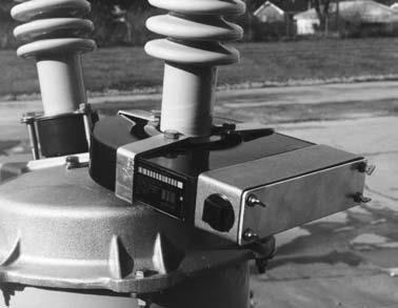
CTs, usually installed in a specialized housing called a CT cabinet, also protect the main lines of the power grid. An overcurrent relay is a type of protective relay (switch) that trips a circuit breaker if a high-voltage current exceeds a certain preset value. Overcurrent relays use a CT to measure the current, since the current of a high-voltage line could not be measured directly.
Cite This Article
MLA
Dohrman, Paul. "What Are The Functions Of A Current Transformer?" sciencing.com, https://www.sciencing.com/functions-current-transformer-5347786/. 14 December 2020.
APA
Dohrman, Paul. (2020, December 14). What Are The Functions Of A Current Transformer?. sciencing.com. Retrieved from https://www.sciencing.com/functions-current-transformer-5347786/
Chicago
Dohrman, Paul. What Are The Functions Of A Current Transformer? last modified March 24, 2022. https://www.sciencing.com/functions-current-transformer-5347786/
