Kirchhoff's Laws (Current & Voltage): What Is It & Why Is It Important?
As electric circuits become more complex with multiple branches and elements, it can become increasingly challenging to determine how much current might be flowing through any given branch and how to adjust things accordingly. It is helpful to have a systematic way of analyzing circuits.
Important Definitions
Important Definitions
In order to understand Kirchhoff's laws, a few definitions are needed:
- Voltage V is the potential difference across a circuit element. It is measured in units of volts (V).
- Current I is a measure of the rate of flow of charge past a point in a circuit. It is measured in units of amperes (A).
- Resistance R is a measure of a circuit element's opposition to current flow. It is measured in units of ohms (Ω).
- Ohm's law relates these three quantities via the following equation: V = IR.
What Are Kirchhoff's Laws?
What Are Kirchhoff's Laws?
In 1845, German physicist Gustav Kirchhoff formalized the following two rules about circuits:
**1. The Junction Rule (also known as Kirchhoff's current law or KCL):** The sum of all currents flowing into a junction in a circuit must equal the total current flowing out of the junction.
Another way this law is sometimes phrased is that the algebraic sum of currents flowing into a junction is 0. This would mean treating any currents flowing into the junction as positive, and any flowing out as negative. Since the total flowing in should equal the total flowing out, it is equivalent to state that the sums would be 0 as this amounts to moving those flowing out to the other side of the equation with a negative sign.
This law is true via a simple application of conservation of charge. Whatever flows in must equal what flows out. Imagine water pipes connecting and branching in a similar way. Just as you would expect the total water flowing into a junction to equal the total water flowing out of the junction, so it is with flowing electrons.
**2. The Loop Rule (also known as Kirchhoff's voltage law or KVL):** The sum of potential (voltage) differences around a closed loop in a circuit must equal 0.
To understand Kirchhoff's second law, imagine what would happen if this wasn't true. Consider a single-circuit loop that has a few batteries and resistors in it. Imagine starting at point A and going clockwise around the loop. You gain voltage as you go across a battery and then drop voltage as you go across a resistor and so on.
Once you've gone all the way around the loop, you end up at point A again. The sum of all of the potential differences as you went around the loop should then equal the potential difference between point A and itself. Well, a single point cannot have two different potential values, so this sum must be 0.
As an analogy, consider what happens if you go on a circular hiking trail. Suppose you start at point A and begin hiking. Part of the hike takes you uphill and part of it takes you downhill and so on. After completing the loop you are back at point A again. It is necessarily the case that the sum of your elevation gains and drops in this closed loop must be 0 precisely because the elevation at point A must equal itself.
Why Are Kirchhoff's Laws Important?
Why Are Kirchhoff's Laws Important?
When working with a simple series circuit, determining the current in the loop requires only knowing the applied voltage and the sum of the resistances in the loop (and then applying Ohm's law.)
In parallel circuits and electrical circuits with combinations of series and parallel elements, however, the task of determining the current flowing through each branch quickly becomes more complicated. Current entering a junction will split as it enters different parts of the circuit, and it isn't obvious how much will go each way without careful analysis.
Kirchhoff's two rules allow for circuit analysis of increasingly complex circuits. While the algebraic steps required are still fairly involved, the process itself is straightforward. These laws are widely used in the field of electrical engineering.
Being able to analyze circuits is important in order to avoid overloading circuit elements. If you don't know how much current is going to flow through a device or what voltage will drop across it, you won't know what the power output will be, and all of this is relevant in the functioning of the device.
How to Apply Kirchhoff's Laws
How to Apply Kirchhoff's Laws
Kirchhoff's rules can be applied to analyze a circuit diagram by applying the following steps:
Step 1
For each branch, i, of the circuit, label the unknown current flowing through it as _Ii_ and choose a direction for this current. (The direction does not need to be correct. If it turns out that this current is actually flowing in the opposite direction, then you will simply get a negative value when solving for this current later.)
Step 2
For each loop in the circuit, choose a direction. (This is arbitrary. You can pick counterclockwise or clockwise. It doesn't matter.)
Step 3
For each loop, start at one point and go around in the chosen direction, adding up the potential differences across each element. These potential differences can be determined as follows:
- If current passes in the positive direction through a voltage source, this is a positive voltage value. If current passes in the negative direction through a voltage source, the voltage should have a negative sign.
- If current passes in the positive direction across a resistive element, then you use Ohm's law and add _-Ii× R (the voltage drop across that resistor) for that element. If current passes in the negative direction across a resistive element, then you add +I i× R_ for that element.
- Once you've made it all the way around the loop, set this sum of all voltages equal to 0. Repeat for all loops in the circuit.
Step 4
For each junction, the sum of the currents flowing into that junction should equal the sum of the currents flowing out of that junction. Write this as an equation.
Step 5
You should now have a set of simultaneous equations that will allow you to determine the current (or other unknown quantities) in all branches of the circuit. The final step is to algebraically solve this system.
Examples
Examples
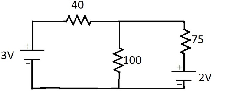
**Example 1:** Consider the following circuit:
na
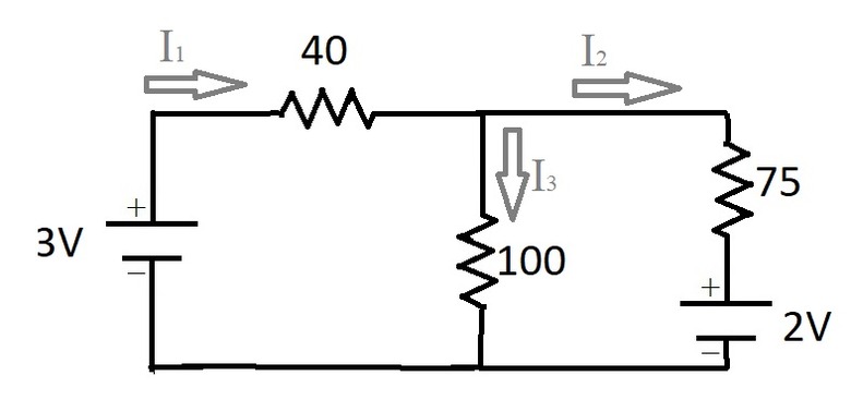
Applying Step 1, for each branch we label the unknown currents.
 na
na
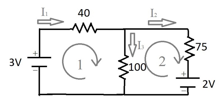
Applying Step 2, we choose a direction for each loop in the circuit as follows:
 na
na
Now we apply Step 3: For each loop, starting at one point and going around in the chosen direction, we add up the potential differences across each element and set the sum equal to 0.
For Loop 1 in the diagram, we get:
\(-I_1\times 40 – I_3\times 100 + 3 = 0\)
For Loop 2 in the diagram, we get:
\(-I_2\times 75 – 2 + I_3\times 100 = 0\)
For step 4, we apply the junction rule. There are two junctions in our diagram, but they both yield equivalent equations. Namely:
\(I_1 = I_2 + I_3\)
Finally, for step 5 we use algebra to solve the system of equations for the unknown currents:
Use the junction equation to substitute into the first loop equation:
\(-(I_2 + I_3)\times 40 – I_3\times 100 + 3 = -40I_2 – 140I_3 + 3 = 0\)
Solve this equation for _I2_:
\(I_2 = \frac{3-140I_3}{40}\)
Substitute this into the second loop equation:
\(-[(3-140I_3)/40]\times 75 – 2 + 100I_3 = 0\)
Solve for _I3_:
\(-3\times 75/40 + (140\times 75/40)I_3 – 2 + 100I_3=0\
\implies\)
\(I_3 = (2+3\times 75/40)/(140\times 75/40 + 100) = 0.021 \text{ A}\)
Use the value of _I3_ to solve for _I2_:
\(I_2 = (3-140\times (0.021))/40 = 0.0015\text{ A}\)
And solve for _I1_:
\(I_1 = I_2 + I_3 = 0.021 + 0.0015 = 0.0225 \text{ A}\)
**So the final result is that _I1_ = 0.0225 A, _I2_ = 0.0015 A and _I3_ = 0.021 A.**
Substituting these current values into the original equations checks out, so we can be fairly confident of the result!
TL;DR (Too Long; Didn't Read)
Because it is very easy to make simple algebraic errors in such calculations, it is highly recommended that you check that your final results are consistent with the original equations by plugging them in and making sure they work.
Consider trying this same problem again, but making a different choice for your current labels and loop directions. If done carefully, you should get the same result, showing that the initial choices are indeed arbitrary.
(Note that if you choose different directions for your labeled currents, then your answers for them will differ by a minus sign; however, the results would still correspond to the same direction and magnitude of current in the circuit.)
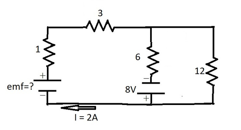
**Example 2:** What is the electromotive force (emf) ε of the battery in the following circuit? What is the current in each branch?
 na
na
First we label all of the unknown currents. Let _I2_ = current down through middle branch and _I1_ = current down through far right branch. The image already shows a current I in the far left branch labeled.
Choosing a clockwise direction for each loop and applying Kirchhoff's circuit laws gives the following system of equations:
\(\begin{aligned}
&I_1 = I-I_2\
&\varepsilon – 4I – 6I_2 + 8 = 0\
&-12I_1 – 8 + 6I_2 = 0 \end{aligned}\)
To solve, substitute _I – I2_ for _I1_ in the third equation, and then plug in the given value for I and solve that equation for _I2_. Once you know _I2_, you can plug I and _I2_ into the first equation to get _I1. Then you can solve the second equation for ε_ . Following these steps gives the final solution:
\(\begin{aligned}
&I_2 = 16/9 = 1.78 \text{ A}\
&I_1 = 2/9 = 0.22 \text{ A}\
&\varepsilon = 32/3 = 10.67\text{ V}
\end{aligned}\)
Again, you should always verify your final results by plugging them into your original equations. It is very easy to make simple algebraic errors!
Cite This Article
MLA
TOWELL, GAYLE. "Kirchhoff's Laws (Current & Voltage): What Is It & Why Is It Important?" sciencing.com, https://www.sciencing.com/kirchhoffs-laws-current-voltage-what-is-it-why-is-it-important-13721186/. 28 December 2020.
APA
TOWELL, GAYLE. (2020, December 28). Kirchhoff's Laws (Current & Voltage): What Is It & Why Is It Important?. sciencing.com. Retrieved from https://www.sciencing.com/kirchhoffs-laws-current-voltage-what-is-it-why-is-it-important-13721186/
Chicago
TOWELL, GAYLE. Kirchhoff's Laws (Current & Voltage): What Is It & Why Is It Important? last modified August 30, 2022. https://www.sciencing.com/kirchhoffs-laws-current-voltage-what-is-it-why-is-it-important-13721186/