Rack-And-Pinion: Gear Ratio
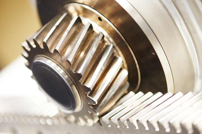
Gear ratio represents the relationship between the number of teeth between the two gears that mesh together. Rack-and-pinion gear ratio is slightly different in that it measures the distance rack travels. This ratio shows the number of revolutions each gear makes relative to the rack it moves on. Rack-and-pinion gears convert rotational motion into linear motion.
Rack-and-Pinion
Rack-and-Pinion
A rack-and-pinion gear system consists of a round gear known as the pinion and a flat, toothed component known as the rack. The principle is the same, but rather than number of rotations, the ratio determines the linear distance traveled by the rack with each rotation of the pinion. Rack-and-pinion gears are used for steering in some automobiles, stairlifts and some trams and railways that have the rack-and-pinion gear set in the middle of the track for climbing steep grades.
Calculating Rack-and-Pinion Gear Ratio
Calculating Rack-and-Pinion Gear Ratio
Instead of counting the number of teeth in each gear, measure the distance the rack moves in inches. Measure the distance from the end of the rack to an arbitrary point, turn the pinion one full revolution and then measure the distance again. The difference between the two is the gear ratio.
Calculating Gear Ratio
Calculating Gear Ratio
For two standard round gears, the gear ratio is calculated by counting the number of teeth on each gear and dividing the number of teeth on the driver gear by the number of teeth on the driven gear. For example, a gear with 25 teeth drives a gear with 75 teeth. Dividing 25 by 75 gives you a ratio of 3/1, meaning that for every three rotations the driver gear makes, the larger gear turns once.
Cite This Article
MLA
Goldstein, Mike. "Rack-And-Pinion: Gear Ratio" sciencing.com, https://www.sciencing.com/rackandpinion-gear-ratio-7308536/. 13 March 2018.
APA
Goldstein, Mike. (2018, March 13). Rack-And-Pinion: Gear Ratio. sciencing.com. Retrieved from https://www.sciencing.com/rackandpinion-gear-ratio-7308536/
Chicago
Goldstein, Mike. Rack-And-Pinion: Gear Ratio last modified March 24, 2022. https://www.sciencing.com/rackandpinion-gear-ratio-7308536/
