How To Reduce Voltage On 12 Volt System To 4 Volt
Two ways to reduce a 12-volt system to 4 volts are to use voltage dividers or Zener diodes.
Voltage dividers are made from resistors placed in series. The input voltage is divided into an output that depends on the value of the resistors used. They obey Ohm's Law, where the voltage is proportional to the current with the resistance as the constant of proportionality.
Zener diodes are diodes that function like DC sources when they are reverse-biased or placed backwards in circuits. They must be used with a current limiting resistor in order to stay within the manufacturer's power requirements.
Voltage Divider
Step 1
Study Ohm's Law for resistors in series. They are used as voltage dividers. The equation for a very basic one with two resistors is Vout = Vin * (R2/(R1 + R2)), where the desired output voltage is measured over R2.
Step 2
Construct a voltage divider that yields 4 volts. Attach the positive side of the 12-volt source to one side of 660-ohm the resistor, which is R1. Connect its free end to one side of the 330-ohm resistor, which is R2. Wire R2's remaining terminal to the negative side of the power supply.
Step 3
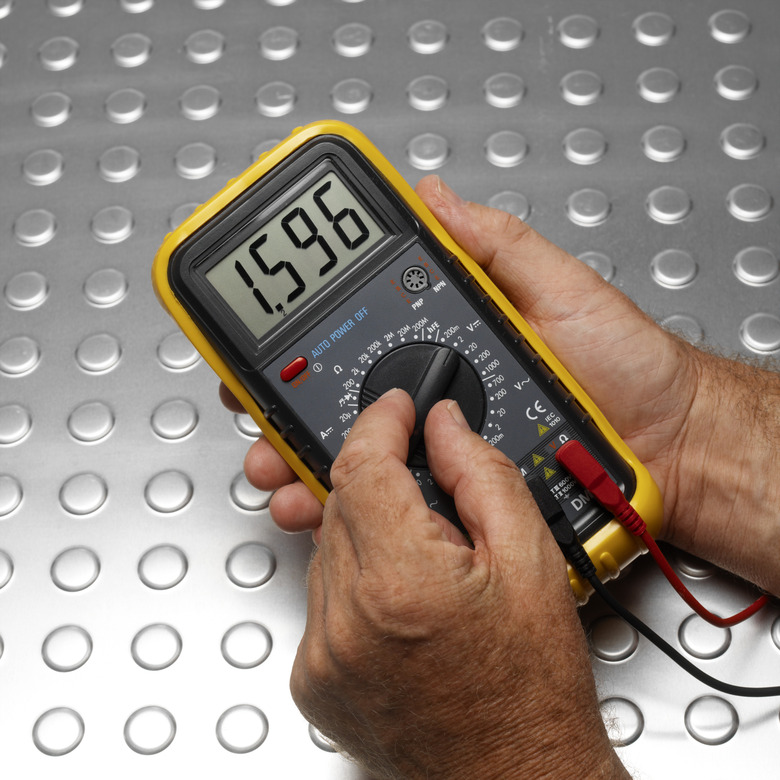
Place the multimeter on a DC voltage setting. Measure the output voltage on R2. Alternatively, measure the output between the two resistors by attaching a wire and placing one probe on it and the other on a wire at ground. The output should be approximately 4 volts.
Zener Diode Regulator
Step 1
Review the specifications and resistance and power formulas for the 1N4731A diode. It outputs a stable 4.3 volts, and has a 1-watt power rating. It also has a maximum Izm current of 1 W/ 4.3 V = 233 mA. The maximum Zener current using the 330-ohm resistor is (Vin – Vout)/R = 12 V – 4.3 V/330 ohm = 23 mA. This is within Izm and also within the diode's power rating, since P = IV = 23 mA*4.3 V = 100 mW.
Step 2
Construct a circuit with the Zener diode and the 330-ohm resistor in series. Attach the positive side of the 12-volt power source to one side of the resistor. Wire the resistor's other end to the reverse-biased side of the Zener diode, which is the side indicated by a mark. Connect the remaining diode terminal to the negative side of the 12-volt source.
Step 3
Measure the voltage across the diode by placing a multimeter lead on each terminal. It should read approximately 4.3 volts.
Things Needed
- 330 and 660-ohm resistors
- 1N4731A Zener diode
- 1N4731A datasheet
- 12-Volt power supply or equivalent
- Digital multimeter
- Breadboard
- Jumper wires
- Basic electronics text
TL;DR (Too Long; Didn't Read)
The Zener diode may be paired with an op-amp emitter-follower circuit if higher output current is needed.
These calculations do not factor in the Zener resistance, which is important for precision measurements.
Warning
The Zener must be reverse-biased, or else it will behave like a regular silicon diode.
Semiconductors are sensitive devices. Be sure not to exceed the power, current and temperature ratings specified by the manufacturer.
Always exercise caution when building electrical circuits to avoid burning yourself or damaging your equipment.
References
- Electronic Principles; Albert Malvino; 1999
- Getting Started in Electronics; Forrest Mims III; 2000
- The Art of Electronics; Paul Horowitz and Winfield Hill; 1997
Cite This Article
MLA
Lewis, Kim. "How To Reduce Voltage On 12 Volt System To 4 Volt" sciencing.com, https://www.sciencing.com/reduce-12-volt-system-volt-5819671/. 24 April 2017.
APA
Lewis, Kim. (2017, April 24). How To Reduce Voltage On 12 Volt System To 4 Volt. sciencing.com. Retrieved from https://www.sciencing.com/reduce-12-volt-system-volt-5819671/
Chicago
Lewis, Kim. How To Reduce Voltage On 12 Volt System To 4 Volt last modified March 24, 2022. https://www.sciencing.com/reduce-12-volt-system-volt-5819671/