Resistance: Definition, Units, Formula (W/ Examples)
Understanding the role of resistance in an electrical circuit is the first step toward understanding how circuits can power various devices. Resistive elements impede the flow of electrons, and in doing so, they allow electric energy to be converted into other forms.
Definition of Resistance
Definition of Resistance
Electrical resistance is a measure of opposition to the flow of electric current. If you consider electrons flowing through a wire as analogous to marbles rolling down a ramp, resistance is what would happen if obstructions were placed on the ramp, causing the flow of marbles to slow as they transfer some of their energy to the obstructions.
Another analogy would be to consider flowing water slowing as it passes through a turbine in a hydroelectric generator, causing it to churn as energy is transferred from the water to the turbine.
The SI unit of resistance is the ohm (Ω) where 1 Ω = kg⋅m2⋅s−3⋅A−2.
Formula for Resistance
Formula for Resistance
Resistance of a conductor can be calculated as:
\(R = \frac{ρ L}{A}\)
where ρ is the resistivity of the material (a property dependent upon its composition), L is the length of the material and A is the cross-sectional area.
Resistivity for different materials can be found in the following table: https://www.physicsclassroom.com/class/circuits/Lesson-3/Resistance
Additional resistivity values can be looked up in other sources.
Note that resistance decreases when a wire has a larger cross-sectional area A. This is because the wider wire can allow more electrons through. Resistance increases as wire length increases because the larger length creates a longer path full of resistivity that wants to oppose the flow of charge.
Resistors in an Electric Circuit
Resistors in an Electric Circuit
All circuit components have a certain amount of resistance; however, there are elements specifically called resistors that are often placed in a circuit to adjust the current flow.
These resistors often have colored bands on them that indicate their resistance. For example, a resistor with yellow, violet, brown and silver bands would have a value of 47 × 101 =470 Ω with 10 percent tolerance.
Resistance and Ohm's Law
Resistance and Ohm's Law
Ohm's law states that voltage V is directly proportional to current I where the resistance R is the constant of proportionality. As an equation, this is expressed as:
\(V=IR\)
Since the potential difference in a given circuit comes from the power supply, this equation makes it clear that using different resistors can directly adjust the current in a circuit. For a fixed voltage, high resistance creates lower current, and low resistance causes higher current.
Non-Ohmic Resistors
Non-Ohmic Resistors
A non-ohmic resistor is a resistor whose resistance value does not remain constant, but instead varies depending on the current and the voltage.
An ohmic resistor, in contrast, has a constant resistance value. In other words, if you were to graph V vs. I for an ohmic resistor, you would get a linear graph with a slope equal to the resistance R.
If you created a similar graph for a non-ohmic resistor, it would not be linear. This does not mean, however, that the relationship V = IR no longer applies; it still does. It just means that R is no longer fixed.
What makes a resistor non-ohmic is if increasing the current through it causes it to heat up significantly or emit energy in some other way. Light bulbs are excellent examples of non-ohmic resistors. As the voltage across a light bulb increases, so too does the resistance of the bulb (as it slows the current by converting electrical energy into light and heat). The voltage vs. current graph for a light bulb typically has an increasing slope as a result.
Effective Resistance of Resistors in Series
Effective Resistance of Resistors in Series
We can use Ohm's law to determine the effective resistance of resistors connected in series. That is, resistors connected end to end in a line.
Suppose you have n resistors, _R1, R2, ...Rn_ connected in series to a power source of voltage V. Since these resistors are connected end to end, creating one single loop, we know that the current passing through each of them must be the same. We can then write an expression for the voltage drop _Vi_ across the ith resistor in terms of _Ri_ and current I:
\(V_1=IR_1\V_2=IR_2\...\V_n=IR_n\)
Now the total voltage drop across all resistors in the circuit must sum to the total voltage supplied to the circuit:
\(V=V_1+V_2+...+V_n\)
The effective resistance of the circuit should satisfy the equation V = IReff where V is the power source voltage and I is the current flowing from the power source. If we replace each _Vi_ with the expression in terms of I and _Ri_, and then simplify, we get:
\(V = V_1+V_2+...+V_n= I(R_1 + R_2 +...+ R_n)=IR_{eff}\)
Hence:
\(R_{eff}=R_1 + R_2 +...+ R_n\)
This is nice and simple. The effective resistance of resistors in series is just the sum of the individual resistances! The same is not true, however, for resistors in parallel.
Effective Resistance of Resistors in Parallel
Effective Resistance of Resistors in Parallel
Resistors connected in parallel are resistors whose right-hand sides all join at one point in the circuit, and whose left-hand sides all join at a second point in the circuit.
Suppose we have n resistors connected in parallel to a voltage source V. Since all resistors are connected to the same to points, which are directly connected to the voltage terminals, then the voltage across each resistor is also V.
Current through each resistor can then be found from Ohm's law:
\(V = IR \implies I = V/R\)
\(\begin{aligned}
\text{So } &I_1 = V/R_1\
&I_2=V/R_2\
&...\
&I_n=V/R_n
\end{aligned}\)
Whatever the effective resistance is, it should satisfy the equation V = IReff, or equivalently I = V/Reff, where I is the current flowing from the power source.
Since the current coming from the power source branches as it enters the resistors, and then comes back together again, we know that:
\(I = I_1+I_2+...+I_n\)
Substituting our expressions for _Ii_ we get:
\(I =V/R_1 + V/R_2 +...+V/R_n=V(1/R_1 + 1/R_2+...+1/R_n) = V/R_{eff}\)
Hence we get the relationship:
\(1/R_{eff}=1/R_1 + 1/R_2+...+1/R_n\
\text{or}\
R_{eff}=(1/R_1 + 1/R_2+...+1/R_n)^{-1}\)
One thing to notice about this relationship is that once you start adding resistors in series, the effective resistance becomes less than any single resistor. This is because by adding them in parallel, you are giving the current more paths through which to flow. This is similar to what happens when we widen the cross-sectional area in the formula for resistance in terms of resistivity.
Power and Resistance
Power and Resistance
Power dissipated across a circuit element is given by P = IV where I is the current through the element and V is the potential drop across it.
Using Ohm's law, we can derive two additional relationships. First, by replacing V with IR, we get:
\(P = I(IR) = I^2R\)
And second, by replacing I with V/R we get:
\(P = V/R(V) = V^2/R\)
Examples
Examples
**Example 1:** If you were to place a 220 Ω, 100 Ω and 470 Ω resistor in series, what should the effective resistance be?
In series, the resistances simply add, so the effective resistance would be:
\(R_{eff}=220 + 100 + 470 = 790\text{ }\Omega\)
**Example 2:** What would the effective resistance of the same set of resistors be in parallel?
Here we use the formula for parallel resistance:
\(R_{eff} = (1/220+1/100+1/470)^{-1} = 60 \text{ }\Omega\)
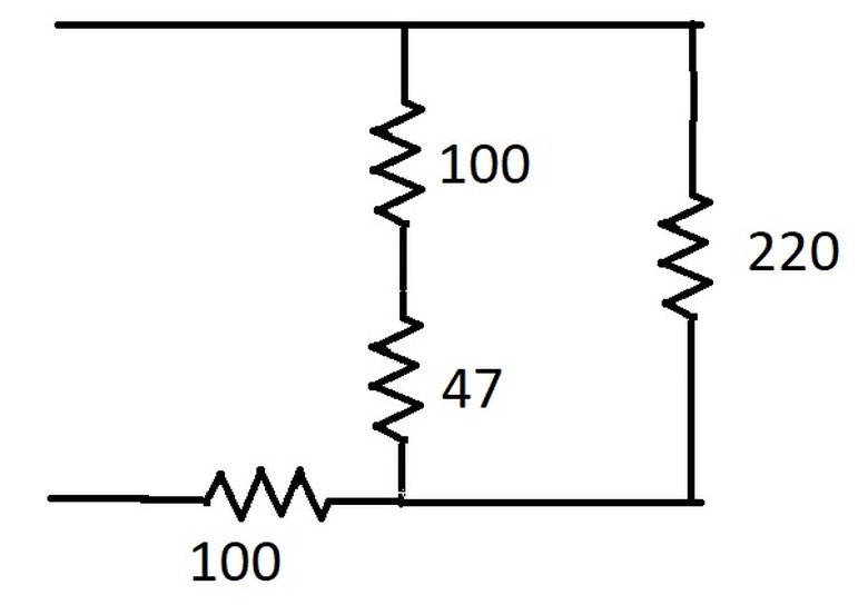
**Example 3:** What would the effective resistance be of the following arrangement:
na
First we have to sort out the connections. We have a 100 Ω resistor connected to a 47 Ω resistor in series, so the combined resistance of those two becomes 147 Ω .
But that 147 Ω is in parallel with 220 Ω, creating a combined resistance of (1/147 + 1/220)-1 = 88 Ω.
Finally that 88 Ω is in series with the 100 Ω resistor, making the result 100 + 88 = 188 Ω.
**Example 4:** How much power is dissipated across the set of resistors in the previous example when connected to a 2 V source?
We can use the relationship P = V2/R to get P = 4/188 = 0.0213 watts.
Cite This Article
MLA
TOWELL, GAYLE. "Resistance: Definition, Units, Formula (W/ Examples)" sciencing.com, https://www.sciencing.com/resistance-definition-units-formula-w-examples-13721183/. 28 December 2020.
APA
TOWELL, GAYLE. (2020, December 28). Resistance: Definition, Units, Formula (W/ Examples). sciencing.com. Retrieved from https://www.sciencing.com/resistance-definition-units-formula-w-examples-13721183/
Chicago
TOWELL, GAYLE. Resistance: Definition, Units, Formula (W/ Examples) last modified August 30, 2022. https://www.sciencing.com/resistance-definition-units-formula-w-examples-13721183/