How To Test A 2N3055 Transistor
The 2N3055 transistor, like all transistors, is essentially an electronic switch. Because the 2N3055 is a bipolar junction transistor, its three terminals are called the base, the collector and the emitter. A voltage applied through a resistor to the base can control the current flowing from the collector to the emitter. There are numerous characteristics of a transistor that are important for particular applications; however, you can test the basic functionality of the 2N3055 by operating it as a simple switch.
Step 1
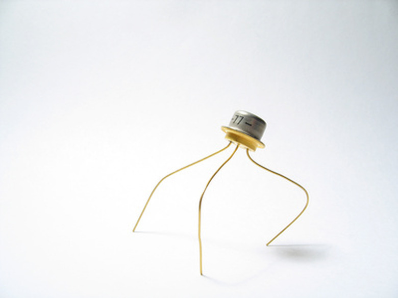
Identify the base, collector and emitter of your transistor. The 2N3055 usually comes in a metal case with two pins. Pin 1 is the base, pin 2 is the emitter and the collector is connected to the metal case.
Step 2
Insert the transistor into your breadboard. If the leads on the transistor are too large for your breadboard contacts, you will need to attach wires to the leads and insert the wires into the breadboards. Ensure that the three transistor terminals are not connected to the same contact strip (the contact strips usually run vertically). This would short out the transistor.
Step 3
Insert a 1 k-ohm resistor into the breadboard. Arrange it so one lead is connected to the base of the transistor.
Step 4
Insert a 100 ohm resistor into the breadboard. Arrange it so one lead is connected to the collector of the transistor.
Step 5
Connect one positive supply voltage to the unconnected lead of the base resistor, and connect the other positive supply voltage to the unconnected lead of the collector resistor. These connections can be made with wires or with clip cables that plug into the power supply.
Step 6
Connect the negative terminals of the supply voltages to one of the long "bus" strips on the breadboard (these usually run horizontally at the top and bottom of the breadboard). This provides a "ground rail."
Step 7
Insert a wire that connects the emitter of the transistor to the ground rail.
Step 8
Turn on the power supply. Set the collector voltage supply to 10 Volts and the base supply to 0 Volts.
Step 9
Touch the probes of the voltmeter to the leads of the collector resistor. The voltage should be zero volts, because with no base voltage, the transistor is turned off, so no current is passing through the resistor.
Step 10
Gradually increase the voltage supply that is connected to the base resistor, and watch the reading on the voltmeter. The base-emitter voltage of the 2N3055 is about 1.8 Volts. As the voltage supply approaches 1.8 Volts, the transistor should start to turn on. As this happens, current is driven through the collector resistor, so a voltage should appear across this resistor. This voltage should increase as you continue to increase the supply past 1.8 Volts.
Things Needed
- Breadboard (also called prototyping board)
- Short lengths of wire
- Resistors
- Voltmeter
- Voltage supply with two outputs
TL;DR (Too Long; Didn't Read)
If your voltage reading is negative, you need to swap the red and black probes of the voltmeter.
Cite This Article
MLA
West, Joseph. "How To Test A 2N3055 Transistor" sciencing.com, https://www.sciencing.com/test-2n3055-transistor-7514850/. 24 April 2017.
APA
West, Joseph. (2017, April 24). How To Test A 2N3055 Transistor. sciencing.com. Retrieved from https://www.sciencing.com/test-2n3055-transistor-7514850/
Chicago
West, Joseph. How To Test A 2N3055 Transistor last modified March 24, 2022. https://www.sciencing.com/test-2n3055-transistor-7514850/