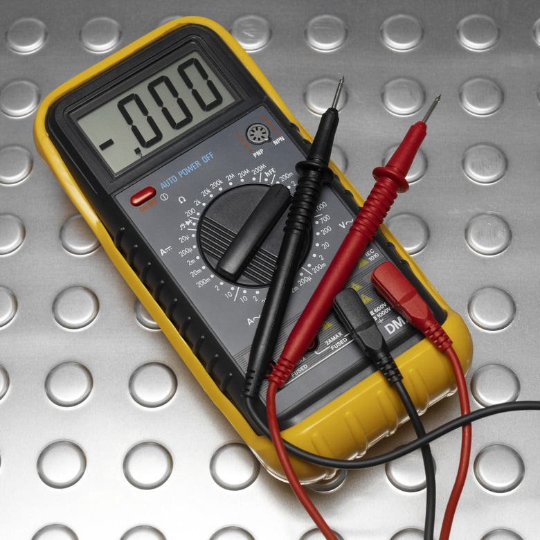
How To Test A 3-Phase Motor With A Multi-Meter
A three-phase motor converts electricity into mechanical energy via an alternating current provided by three leading power wires. The electricity is fed into the interior of the motor, where it creates a magnetic field that pushes the strator and makes it rotate, turning the motor shaft. Three-phase motors require testing with a multimeter during installation and inspections. The multimeter detects the flow of electricity and determines whether it is correct, as the wrong alternating current pattern can cause the motor strator to move the wrong way and malfunction.
Step 1
Select the Phase Rotation setting on your mutlimeter.
Step 2
Inspect the three-phase motor and look for terminals — where three wires connect to the motor — labeled L1, L2 and L3. Connect the meter jacks that are similarly labeled (L1, L2, L3) to the power wires.
Step 3
Observe the display on your multimeter. The display will read "OK" if the power feed is flowing in the correct direction. If it reads "ER", this means that the power feed has been reversed, which causes the motor to turn in the wrong direction.
Step 4
Fix the reversed power feed by first turning off the motor and unplugging it. Switch the position of two of the wires — the order doesn't matter — then reattach the mulitmeter leads to the wires. Turn on the motor. The mulitmeter should read "OK." This means that the 3-phase motor is turning in the correct direction and running correctly.
Cite This Article
MLA
Rohlin, Alexis. "How To Test A 3-Phase Motor With A Multi-Meter" sciencing.com, https://www.sciencing.com/test-3phase-motor-multimeter-12191893/. 24 April 2017.
APA
Rohlin, Alexis. (2017, April 24). How To Test A 3-Phase Motor With A Multi-Meter. sciencing.com. Retrieved from https://www.sciencing.com/test-3phase-motor-multimeter-12191893/
Chicago
Rohlin, Alexis. How To Test A 3-Phase Motor With A Multi-Meter last modified March 24, 2022. https://www.sciencing.com/test-3phase-motor-multimeter-12191893/
