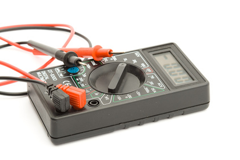
How To Test A Blower Resistor
All electrical devices contain circuits that channel current to perform various tasks. To limit the amount of electrical current flowing through a part of a circuit, engineers use resistors. The effectiveness of a given resistor is measured in ohms. The more ohms of resistance a resistor has, the less current is allowed to flow in the circuit. This is referred to as Ohm's Law. A resistor typically has its resistance as well as a tolerance written on it. Tolerance is the amount above or below the labeled number of ohms the resistance may actually be.
Step 1
Turn on the digital multimeter.
Step 2
Rotate the reading dial to the resistance setting. This is designated by the capital Greek letter "omega," which stands for ohms.
Step 3
Touch the black multimeter probe to the wire coming out of the left side of the resistor.
Step 4
Connect the red multimeter probe to the wire coming out of the right side of the resistor. Note the reading on the screen. If the reading lies within the given tolerance range of the resistor, it is functioning properly. For example, a 200 ohm resistor with a tolerance of 5 ohm should have a multimeter reading between 195 and 205 ohms if it is working correctly.
References
- "Physics for Scientists and Engineers with Modern Physics"; Raymond A. Serway and John W. Jewett; 2009
- Georgia State University: HyperPhysics: Resistance
- Georgia State University: HyperPhysics: Ohm's Law
Cite This Article
MLA
Hirsch, William. "How To Test A Blower Resistor" sciencing.com, https://www.sciencing.com/test-blower-resistor-7627151/. 24 April 2017.
APA
Hirsch, William. (2017, April 24). How To Test A Blower Resistor. sciencing.com. Retrieved from https://www.sciencing.com/test-blower-resistor-7627151/
Chicago
Hirsch, William. How To Test A Blower Resistor last modified March 24, 2022. https://www.sciencing.com/test-blower-resistor-7627151/
