How To Test Diodes In Circuit
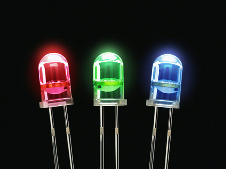
A diode is a bipolar semiconductor that only allows current to pass in one direction. The positive terminal of a diode is called the anode, and the negative terminal is called the cathode. You can damage a diode by exceeding its rated voltage or current values. Often, a failed diode will allow current to pass in either direction unimpeded. You can test a diode using a multimeter. There are many different styles and brands of multimeter, but they all function essentially the same way and offer similar features. A digital multimeter has an LCD display that prints the value, and an analog multimeter uses a needle and a scale.
Using a Digital Multimeter
Step 1
Connect the banana plugs of the two probes to your multimeter, if your multimeter uses removable probes. Connect the red probe to the red jack and the black probe to the jack labeled "COM" (for common, another term for ground.
Step 2
Turn the dial on you multimeter to the "diode" setting. The "diode" setting is usually identified by the schematic symbol for a diode, a triangle pointing at a line.
Step 3
Identify the cathode of the diode you want to test. The cathode is marked by a colored band around one end of the diode. The other end of the diode is called the anode.
Step 4
Connect the red probe to the anode and the black probe to the cathode. This way the diode is forward biased, so if it's working properly it should conduct. Your multimeter should display a voltage reading. The voltage value itself is irrelevant, as long as it's present. If your meter displays no voltage or an error message, either you mixed up the anode and the cathode or the diode is broken.
Step 5
Reverse the probes, so that the red probe is connected to the cathode and the black probe is connected to the anode. The diode should not conduct this way. If the diode is working, your meter should display some kind of "off the scale" or "out of range" message. The exact message will vary from meter to meter. If your meter displays a voltage reading, the diode has failed.
Using an Analog Multimeter
Step 1
Connect the red probe to the positive terminal of the multimeter, and the black probe to the ground terminal of the multimeter, same as with a digital meter.
Step 2
Turn the dial on the meter to test a low resistance range, such as 10 ohms or similar, depending on what's available on your meter.
Step 3
Connect the black probe to the anode of the diode and the red probe to the cathode. With an analog meter, the polarity of the probes is reversed when you're testing resistance. If the diode is working, it should conduct, so the dial should indicate a low resistance value. The exact resistance value displayed is irrelevant. If the meter indicates maximum resistance, with the needle all the way to the left, then you either have the anode and cathode mixed up or the diode is broken.
Step 4
Switch the probes so that the red probe is connected to the anode and the black probe is connected to the cathode. The diode should not conduct at all this way, so the meter should indicate full resistance, with the needle all the way to the left. If the meter indicates that the diode is conducting, then the diode has failed.
References
Cite This Article
MLA
Quaid, Douglas. "How To Test Diodes In Circuit" sciencing.com, https://www.sciencing.com/test-diodes-circuit-7424865/. 24 April 2017.
APA
Quaid, Douglas. (2017, April 24). How To Test Diodes In Circuit. sciencing.com. Retrieved from https://www.sciencing.com/test-diodes-circuit-7424865/
Chicago
Quaid, Douglas. How To Test Diodes In Circuit last modified March 24, 2022. https://www.sciencing.com/test-diodes-circuit-7424865/