How To Use A Cen-Tech Digital Multimeter
Cen-Tech manufactures several different digital multimeters, but you don't need separate instructions for each one. If you know how to use the inexpensive 98025 seven-function model, you can use all the others. The seven functions refer to this model's ability to measure AC and DC voltage, current and resistance, and its ability to test diodes, transistors and batteries.
Getting Ready to Use the Multimeter
Getting Ready to Use the Multimeter
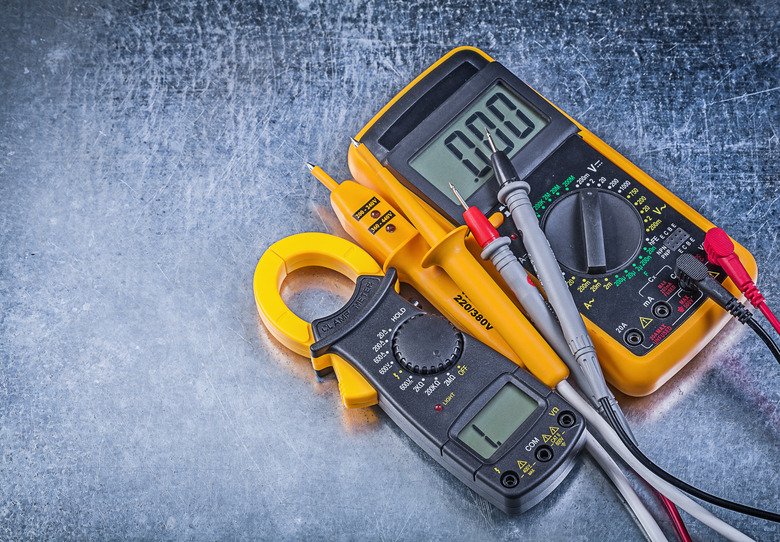
Note the main selector wheel on the front of the multimeter. Use this wheel to select the function you need and the sensitivity of the measurement you're going to make. You'll notice three jack inputs arranged in a vertical line on the bottom right. They are marked – from top to bottom – 10ADC, VΩmA and COM. The meter comes with a pair of leads, one black and one red, that fit into these jacks. On the left side, you'll see a multipin transistor /hFE jack for testing transistors. You'll also see an On/Off button. Turn this on to activate the LED display.
Measuring Voltage and Current
Measuring Voltage and Current
To measure AC voltage, rotate the selector to point to 750 in the AC voltage section (ACV) at the top. Plug the red lead into the jack marked VΩmA and the black lead into the jack marked COM. Touch the leads to the exposed wires of the circuit you are testing and note the reading. If it is less than 250 volts, turn the selector to the 250 setting in the AC voltage section to get a more accurate reading.
To measure DC voltage, leave the red lead in the jack marked VΩmA and the black lead in the jack marked COM and turn the dial counterclockwise to the 1000 setting in the DC voltage section (DCV). Take the reading by touching the leads to the exposed circuit wires. If the reading is less than 200, move the dial to that setting. If the reading is less than 20, move the dial to that setting. Keep turning the dial as needed, all the way to 200 mV if necessary, to get the most accurate reading.
To measure current, switch the red lead to the 10 ADC jack and leave the black one in the COM jack. Turn the dial to the 10 amp (10A) area, make sure the meter is on, touch the leads to the exposed circuit wires and note the reading. If it's below 0.2 amps, turn off the meter, place the red lead into the VmA jack and turn the dial one position counterclockwise to the 220m setting in the DC amp (DCA) area. Turn on the meter and take another reading. Continue turning the dial counterclockwise – all the way to 200 µ if necessary – to increase the accuracy of the reading.
Measuring Resistance and Continuity
Measuring Resistance and Continuity
When you measure resistance, the unit supplies a small current, so there must be no other current source. Check the circuit with the voltage function to make sure the meter reads 0. Insert the red lead in the VΩmA jack and the black lead in COM. Turn on the multimeter and move the selector to the 200 position in the ohm (Ω) area. Before you take a measurement, touch the leads together and make sure the meter reads 0, indicating there is no resistance between the leads. Touch the leads to the exposed circuit wires and note the reading. If the reading is 1, turn the dial one position counterclockwise and try again. Keep turning the dial – all the way to 2000k if necessary – until you get a reading other than 1.
You can use the resistance function to test for continuity. Set the dial to the 2000k position in the ohm section and measure the circuit as you would for resistance. If the reading is 1, the circuit is open. Any other reading indicates a closed circuit.
Testing Diodes, Batteries and Transistors
Testing Diodes, Batteries and Transistors
You can use the multimeter to test the voltage drop across a diode so you can compare it to the diode's specifications and determine whether it's still good. Turn the dial to the diode section, which is at the 6 o'clock position next to the lowest setting in the ohm section. Insert the red lead into the VΩmA jack and the black lead into COM. Turn on the meter. Touch the red lead to one terminal of the diode and the black lead to the other and note the reading, which is displayed in millivolts. If the reading is 1, reverse the leads and try again.
You can test 9V, D-cell, C-cell, AA and AAA batteries with this meter. Turn the dial to the battery section at the top of the menu to the right of the ACV section. Put the red lead into the VΩmA jack and the other lead into the COM jack and turn on the meter. Touch the red lead to the positive terminal of the battery and the black lead to the negative terminal and note the reading. Do not test 6V or 12V vehicle batteries with this function. Use the voltmeter instead.
To test a transistor, turn the dial to the hFE setting, which is to the right of the diode setting. Plug the transistor into the multipin NPN/PNP jack. To get the proper orientation, you may have to consult the transistor manual. Turn on the meter, note the reading and compare it to the specifications for that transistor.
Warning
Never touch the exposed metal leads with your fingers when taking a measurement.
Turn off the multimeter before switching functions.
Do not use this meter to test voltage on circuits higher than 750V AC or 1,000V DC. Do not test current on circuits higher than 200 mA.
Cite This Article
MLA
Deziel, Chris. "How To Use A Cen-Tech Digital Multimeter" sciencing.com, https://www.sciencing.com/use-centech-digital-multimeter-6101228/. 13 March 2018.
APA
Deziel, Chris. (2018, March 13). How To Use A Cen-Tech Digital Multimeter. sciencing.com. Retrieved from https://www.sciencing.com/use-centech-digital-multimeter-6101228/
Chicago
Deziel, Chris. How To Use A Cen-Tech Digital Multimeter last modified March 24, 2022. https://www.sciencing.com/use-centech-digital-multimeter-6101228/